
Automatic light dimmer circuit

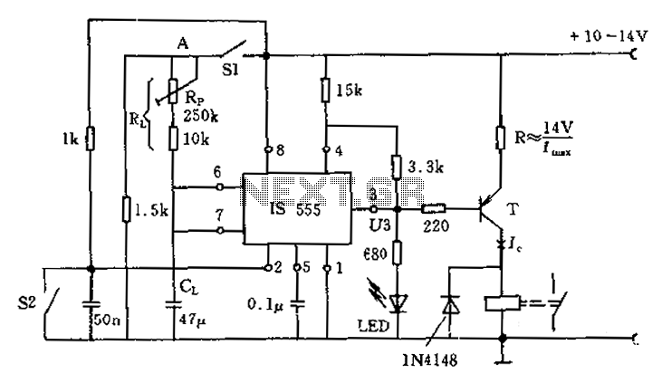
The automatic light dimmer circuit operates based on the principle of varying light intensity. The core component, the light-dependent resistor (LDR), changes its resistance according to the amount of ambient light it receives. In bright conditions, the resistance of the LDR decreases, which triggers the circuit to dim the lights. Conversely, in low-light conditions, the resistance increases, prompting the circuit to brighten the lights.
The circuit typically includes a power source, an LDR, a transistor or operational amplifier for signal processing, and a dimming mechanism such as a triac or a PWM (Pulse Width Modulation) controller. The LDR is connected in a voltage divider configuration with a fixed resistor, allowing the circuit to produce a voltage signal that corresponds to the light intensity. This voltage is then fed into the base of a transistor, which controls the current flowing to the light source.
In practical applications, the circuit can be integrated into various lighting systems, such as streetlights, indoor lighting, or decorative lights, enhancing energy efficiency and user comfort. The automatic light dimmer circuit is particularly beneficial in settings where lighting needs to adjust based on time of day or occupancy, thereby optimizing power consumption and extending the lifespan of light bulbs.
Overall, this circuit exemplifies a simple yet effective solution for automated lighting control, leveraging basic electronic components to achieve functionality that enhances convenience and efficiency in everyday environments.This is an automatic light dimmer circuit. You do not need to dim the lights by yourself. It is so very convenient, because we use the LDR to detect external.. 🔗 External reference
Related Circuits
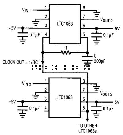
The LTC1063 is a monolithic low-pass filter that provides exceptional DC and AC performance. It features both internal and external clock tunability, with cutoff frequencies reaching up to 50 kHz, a typical output DC offset of 1 mV, and...
Siren Circuit. This circuit generates a sound siren when switch S1 is pressed, increasing the sound frequency as capacitor C1 charges. The sound frequency decreases when switch S1 is released. The siren circuit operates based on the charging and discharging...
The following circuit is an enhanced version of the original Lightning Detector designed to operate on a 5-volt supply. This updated circuit incorporates a refined RF section with a single resonance near 300 kHz and increased sensitivity. The use...
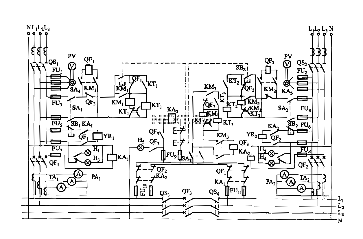
Dual power is provided for each complex, as the load is supplied through a two-way power system. In the event of a power outage, the contact switches transition from a closed position, allowing the power supply circuit to bear...
The circuit for the photoelectric switch S1 functions as a control switch for the luggage room light. In its closed operating state, the voltage is positive. If S2 is closed, irrespective of the state of S1, the output terminal...
This is a simple two-transistor lamp flasher circuit that can be used to flash a 6-volt lamp. The circuit is compact and can be easily fitted into a small enclosure. It utilizes two transistors: one is an NPN BC549,...