
lamp flasher circuit

The two-transistor lamp flasher circuit operates on the principle of astable multivibrator configuration, which provides a square wave output to control the flashing of the lamp. The NPN transistor (BC549) and the PNP transistor (BC556) are configured in such a way that they alternately turn on and off, creating a pulsing effect that causes the connected lamp to flash.
The circuit requires a few additional components, including resistors and capacitors, to set the timing for the flashing effect. The timing can be adjusted by changing the values of these passive components. Typically, a capacitor is connected between the collector of the NPN transistor and the base of the PNP transistor, while another resistor is connected from the collector of the PNP transistor to the base of the NPN transistor. This feedback loop is crucial for the oscillation process that drives the flashing.
The power supply for this circuit is a 6-volt DC source, which can be provided by batteries or a regulated power supply. The circuit's compact design allows it to be housed in various enclosures, making it suitable for applications where space is limited.
When designing this circuit, it is essential to ensure that the transistors are appropriately rated for the current and voltage levels involved, particularly for the lamp being used. The BC549 and BC556 transistors are suitable for low to moderate power applications, making them ideal for driving small lamps in this configuration.
Overall, this two-transistor lamp flasher circuit is an effective and straightforward solution for creating a flashing light effect, suitable for decorative lighting, indicators, or signaling applications.This is a simple two transistor lamp flasher circuit, which can be used to flash 6 volt lamp. The circuit is so small and can be easily fitted in a small box. The circuit is using two transistor one is NPN BC549 and the other is PNP BC556. The input voltage is 6 volt DC. 🔗 External reference
Related Circuits
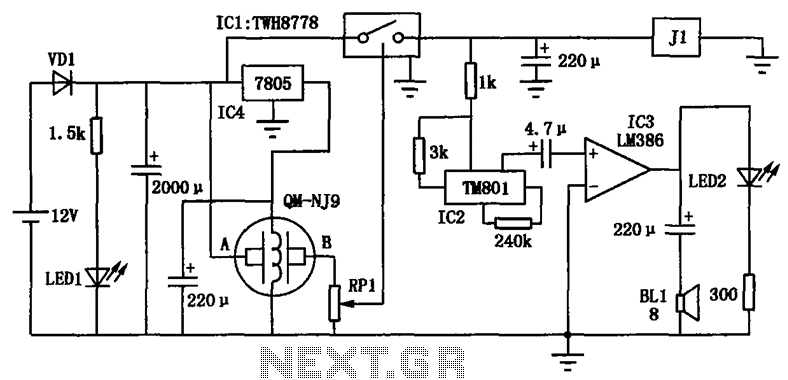
The alcohol detection alarm controller circuit is illustrated in the figure. It utilizes the QM-NJ9 alcohol gas sensor, which detects the presence of alcohol vapors. When alcohol is detected, the resistance between the AB-QM-NJ9 decreases, causing the wiper of...

Any number of normally-open switches may be utilized. Install "tilt" switches that close when the steering is moved or when the bike is lifted off its side-stand or pushed forward off its centre-stand. Employ micro-switches to secure removable panels...
It's a very simple circuit, for the follow-up of baby. It can however be also used for other use, as intercom etc. In the place of M1 we can we use a simple electret mic capsule. The regulation of...
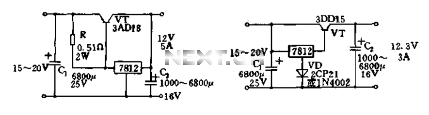
Expand integrated three-terminal regulator block circuit output current method The integrated three-terminal regulator is a versatile component commonly used in power supply circuits to provide a stable output voltage. This regulator typically consists of three terminals: input, output, and ground....

This open-source thread focuses on the development of a "MOSFET Heating Circuit," which is a modified version of an existing design. The MOSFET Heating Circuit is designed to efficiently manage and control heating elements using MOSFET technology. MOSFETs (Metal-Oxide-Semiconductor Field-Effect...

The AA-7 active antenna consists of two active components: Q1 (an MFE201 N-channel dual-gate FET) and Q2 (a 2SC2570 VHF silicon transistor), which form the foundation for two independent, switchable RF preamplifiers. The AA-7 active antenna is designed to enhance...