
Siren Circuit

The siren circuit operates based on the charging and discharging characteristics of capacitor C1, coupled with a sound-generating component, typically a piezoelectric speaker or buzzer. When switch S1 is pressed, it completes the circuit, allowing current to flow and charging capacitor C1. As C1 charges, the voltage across it rises, which in turn affects the frequency of oscillation in the circuit. The frequency increases, producing a higher-pitched sound from the speaker.
The circuit may utilize a simple oscillator configuration, such as a 555 timer in astable mode, to generate the sound output. In this configuration, the charging time of C1, determined by the resistor values in the circuit, influences the frequency of the output waveform. As C1 charges, the time period for the output waveform shortens, resulting in a higher frequency sound.
Upon releasing switch S1, the capacitor begins to discharge, leading to a decrease in voltage and a corresponding reduction in frequency, producing a lower-pitched sound. The transition between high and low frequencies creates a siren-like effect, which can be used for alarms or alerts.
To enhance the circuit, additional components such as variable resistors can be incorporated to allow for frequency adjustment, or a diode can be added to control the discharge path of C1, thereby influencing the decay rate of the sound. Proper component selection and values are crucial for achieving the desired siren effects and ensuring stable operation of the circuit.Siren Circuit. This circuit is to generate sound siren when S1 is pressed and increate sound frequency because charged C1, S1 is released when the frequency decreated. 🔗 External reference
Related Circuits
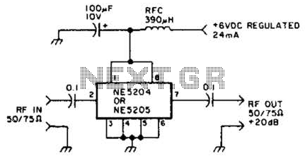
The Signetics NE5204 or NE5205 can be utilized in this audio frequency to 350-MHz (-30 dB) preamplifier. For a requirement of 600 MHz at 3 dB, the NE5205 should be employed. The noise figure is 4.8 dB at 75...
A basic circuit of the 89C2051 shown here can be made easily using point-to-point soldering with a universal PCB. Use an ordinary 20-pin socket, do not use a circle-pin socket. D1 is a small dot LED. U2 can be...
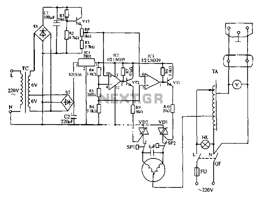
Automatic AC voltage regulator circuit The automatic AC voltage regulator circuit is designed to maintain a stable output voltage despite fluctuations in the input voltage. This circuit is essential for protecting sensitive electronic devices from voltage variations that can lead...
A schematic diagram for a broadband QRP SWR metering circuit intended for use in a QRP antenna tuner. The circuit allows the user to press a momentary DPDT switch to observe an LED indicator while adjusting the capacitors of...
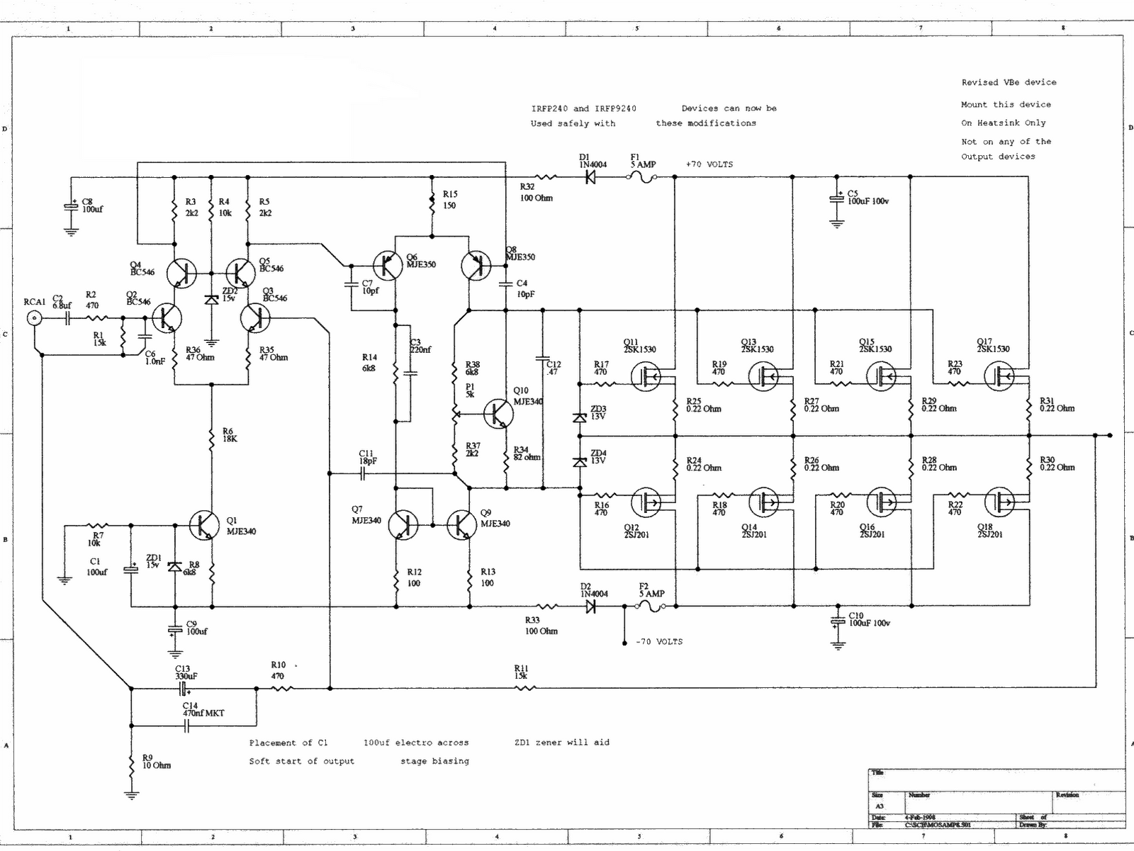
This is a simple LED-powered audio amplifier circuit utilizing a MOSFET amplifier with the TL071C operational amplifier. It can deliver up to 45 W into an 8-ohm load. The circuit incorporates the MOSFETs IRFP240 and IRFP9240, which are recommended...
A wide range auto turn OFF timer covering 1 minute to 20 hours in three ranges with S1. As soon as power is applied to the circuit, the IC1 [555] starts to oscillate and feeds clock pulses to the...