
Automatic Mains Disconnect

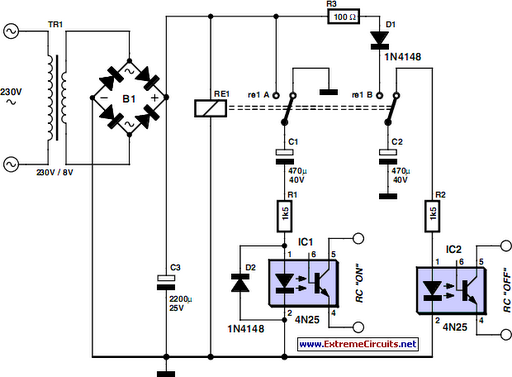
The circuit design incorporates a power relay that acts as a switch for the mains supply to peripheral devices. The relay is activated by a 12-V signal from the PC fan, ensuring that power is only supplied when the PC is operational. The use of an electrolytic capacitor allows for a delayed disengagement of the relay, maintaining power to peripherals briefly after the PC enters sleep mode, thus preventing sudden power loss. The inclusion of diodes D1 and D2 serves to protect the circuit from back EMF generated by inductive loads, such as fans, ensuring reliability and longevity of the components.
When designing the circuit, attention must be paid to the ratings of the relays and switches to ensure they can handle the maximum expected load. The separation of high and low voltage components is not only a safety measure but also essential for the circuit's proper functioning, as it minimizes the risk of interference and potential failure. The enclosure should be robust, providing adequate insulation and protection against accidental contact with live parts. This design can be particularly useful in environments where energy conservation is a priority, as it allows for the complete disconnection of power to peripherals when the PC is not in use.Downloading and CD-burning programs usually provide the option of automatically shutting down the PC on completion of their tasks. However, this energy-saving feature is of little benet if even after the PC has been switched off, all of the peripheral equipment remains connected to the mains and happily consumes watt-hours.
The circuit shown he re provides a solution to this dilemma. It is connected ahead of the power strip and connects or disconnects mains power for all of the equipment via a power relay. A connection to a 12-V PC fan (which may be the processor fan or the fan for the chipset, if the latter is present) indicates whether the PC is switched on.
If you are certain that the 12-V power supply voltage is switched off when the PC is in the sleep mode, you can use this connection instead. To switch everything on, press the Start button to cause the power relay to be energized and provide mains voltage to all of the equipment.
If the PC has an ATX board, its Power switch must be pressed at the same time to cause the PC to start up. When the PC fan starts to run, low-power relay Re1 engages and takes over the function of the Start switch, which can then be released.
This state is stable. If the PC switches to the sleep state, the 12-V voltage drops out. The electrolytic capacitor ensures that Re1 remains engaged for a short time, after which it drops out, followed by the power relay. D1 prevents the electrolytic capacitor from discharging through the connected fan, and D2 is the usual freewheeling diode.
The system is disconnected from both mains leads and is thus completely de-energized. Be sure to select components that are suitable for their tasks. Naturally, the contacts of Re2 should be rated to handle the total current drawn by all of the peripheral equipment and the PC, and the relay coil must be suitable for use with mains voltage (6 mm minimum separation between coil and contacts). A low-power 12-V relay that can switch mains voltage is adequate for Re2. The Start pushbutton switch is connected to the mains voltage, so a 230-V type must be used. The circuit board layout and enclosure must also be designed in accordance with safety regulations. A separation of at least 6 mm must be maintained between all components carrying mains voltage and the low-voltage components, and the enclosure must be completely free of risk of electrical shock.
With a bit of skill, the circuit can betted into a power bar with a built-in switch, if the switch is replaced by a pushbutton switch having the same mounting dimensions. 🔗 External reference
Related Circuits
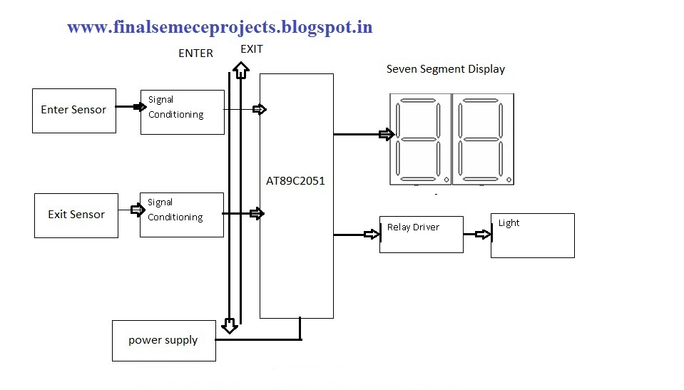
This project involves an automatic room light controller with a bidirectional visitor counter using a microcontroller. It is designed to manage room lighting and accurately count the number of individuals present. When a person enters the room, the counter...
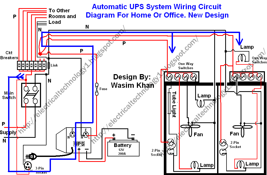
This wiring circuit diagram is designed for providing power to specific rooms in a home or office during a power supply failure. It ensures continuous power supply to devices such as laptops and computers in those particular rooms, especially...

This is an automatic battery charger circuit that utilizes the LM324 integrated circuit, which enhances efficiency. It is capable of charging both 12V and 6V batteries, with filtration managed by switch S1. The circuit is designed to stop charging...
Operating high-beam headlights while driving on highways can significantly enhance visibility; however, it poses a blinding risk to other drivers. This straightforward circuit can be integrated into the headlight switch to facilitate automatic switching between high and low beam...
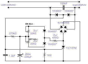
The circuit shown will switch on and off a resistive or inductive load up to 800VA with the possibility to adjust both the on and off period. Switching takes place during the zero crossing of the sine wave. The...
The request for assistance came from an elderly lady in a retirement home. In her room, the light switch by the door and the pull cord above the bed control the ceiling light fitting. However, she prefers to operate...