
Automatic Ni-Cd Battery ChargerCircuit

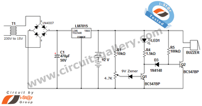
The automatic Ni-Cd battery charger circuit utilizes the NE555 timer IC in a comparator configuration to regulate the charging process. The Zener diode is employed to establish a stable reference voltage of 4.7V, which is crucial for determining the charging state of the battery. This reference voltage is connected to pin 6 of the NE555, while the voltage at pin 2 is monitored to assess the battery's charge level.
During operation, if the voltage at pin 6 surpasses 4.7V, the output at pin 3 transitions to a low state, signaling a reduction in the charging current to prevent overcharging. This feature is essential for maintaining the longevity and safety of the Ni-Cd batteries. On the other hand, if the voltage at pin 2 drops below half of the reference voltage (approximately 2.35V), the NE555 output at pin 3 will increase, allowing more current to flow into the battery for charging.
The circuit typically includes additional components such as resistors and capacitors to ensure stable operation and to filter out any noise that might affect the performance of the NE555 timer. A diode may also be included to prevent reverse current flow, protecting the circuit and the battery from damage.
In summary, this automatic Ni-Cd battery charger circuit effectively monitors and controls the charging process through the use of the NE555 timer IC, ensuring safe and efficient charging of the batteries while extending their operational life.Automatic Ni-Cd Battery Charger circuit is shown in the above picture. The internal comparator of NE555 is set as 4.7V by Zener diode. If the potential of pin 6 becomes higher than this value, the output of pin 3 become lower; if the potential of pin 2 is lower than half of the reference voltage, the output voltage becomes higher,. When the voltage of the.. 🔗 External reference
Related Circuits
This automatic NiCd charger for 9V NiCd batteries utilizes the properties of a 555 timer and is straightforward to construct. The charger is designed to automatically maintain a full charge on the battery, allowing it to remain connected for...
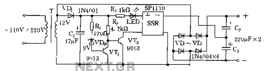
The circuit is automatically converted to a low-voltage configuration. A 220V AC supply is stepped down by transformer T. After this, the breakdown voltage of diode VDw causes transistors VT1 and VT2 to turn off, resulting in the solid-state...
The title contains numerous words because this instructable integrates various concepts from multiple sources. The primary idea originated from Robomaniac's Desktop Energy Seed Lamp, combined with Witch's Growing Plants with LED Lights instructable and various wick gardening planters. The...
This is a straightforward 12V rechargeable smart battery charger circuit. It can be utilized as a charger for car batteries, inverter batteries, emergency light batteries, and more. An automatic indicator alarm circuit accompanies this battery charger schematic. The primary...
Are you unfamiliar with the basics of electronics? An online store has recently opened, offering four excellent books on basic electronics for sale. Reviews of these books are available, and purchases can be made as desired. These books are...
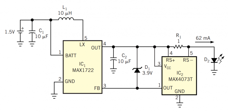
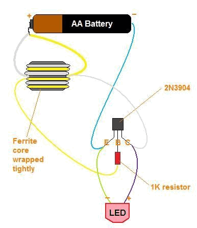
Although white LEDs are common in a variety of lighting applications, their 3 to 4V forward-voltage drop makes low-voltage applications challenging. Charge pumps and other ICs are available for driving white LEDs, but they generally don't work with the...