3 LED battery monitor circuit
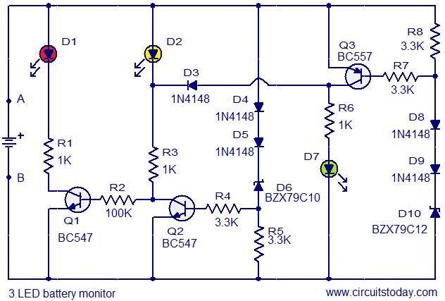
Are you unfamiliar with the basics of electronics? An online store has recently opened, offering four excellent books on basic electronics for sale. Reviews of these books are available, and purchases can be made as desired. These books are utilized by students at some of the world’s top universities. Explore and buy copies here. Additionally, this is the circuit diagram of a 3 LED bar graph type battery monitor circuit, which is ideal for monitoring the voltage level of an automobile battery. When the battery voltage is 11.5V or lower, transistor Q1 will be activated, causing LED D1 to glow. When the battery voltage is between 11.5V and 13.5V, transistor Q2 will be activated, and LED D2 will glow. When the battery voltage exceeds 13.5V, transistor Q3 will be activated, and LED D3 will glow.
The described circuit is a straightforward battery voltage monitoring system utilizing three light-emitting diodes (LEDs) and three bipolar junction transistors (BJTs) to visually indicate the battery voltage levels. The circuit operates within three distinct voltage ranges, each corresponding to a specific LED indicator.
In the first range, when the battery voltage drops to 11.5V or below, transistor Q1 is turned on, which allows current to flow through LED D1, causing it to illuminate. This serves as a warning signal that the battery voltage is critically low, indicating that the battery requires immediate attention or charging.
The second range operates from 11.5V to 13.5V. During this interval, transistor Q2 is activated, illuminating LED D2. This voltage range indicates that the battery is in a moderate state, suggesting that it is functional but may require monitoring to prevent it from falling into a low voltage condition.
In the third range, when the battery voltage exceeds 13.5V, transistor Q3 is turned on, and LED D3 lights up. This indicates that the battery is in a healthy state, typically when it is being charged or is fully charged.
The circuit design is efficient and requires minimal components, making it suitable for both educational purposes and practical applications in automotive environments. The use of BJTs allows for reliable switching, while the LED indicators provide clear visual feedback regarding the battery's state. This design can be easily implemented on a breadboard or printed circuit board (PCB) for prototyping or final deployment.Are you not familiar with the basics of electronics We have just opened an online store where 4 very good books on basic electronics have been kept for sale. You can read the reviews of these books and buy them as you wish. These books are being followed by students in some of the best universities in the world. Check them out and buy copies here :- 4 GREAT BOOKS TO LEARN BASIC ELECTRONICS This is the circuit diagram of a 3 LED bar graph type battery monitor circuit that is ideal for monitoring the voltage level of an automobile battery. When battery voltage is 11. 5V or less transistor Q1 will be On and the LED D1 will be glowing. When battery voltage is between 11. 5 and 13. 5V, the transistor Q2 will be On and the LED D2 will be glowing. When battery voltage is above 13. 5V the transistor Q3 will be On and the LED D7 will be glowing. 🔗 External reference
