
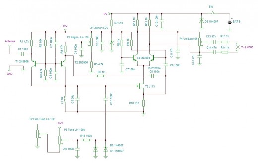
SCA broadcast receiver circuit diagram

The LM567 SCA broadcast reception circuit is an efficient solution for demodulating SCA signals, utilizing the phase-locked loop (PLL) architecture to achieve a stable output. The LM567 integrates various functionalities, including a voltage-controlled oscillator (VCO) that can be adjusted to lock onto the desired frequency. The phase-locked loop works by comparing the phase of the input signal with that of the VCO, adjusting the frequency of the VCO until the two are in sync.
The choice of components is critical for the performance of the circuit. The potentiometer (W) allows for precise adjustments to the VCO frequency, accommodating variations in the input signal and ensuring optimal demodulation of the SCA broadcast. The capacitor (C6) plays a vital role in the stability and response time of the VCO, influencing the overall bandwidth of the demodulation process.
The inductance coil (B) is specifically designed to provide the required inductance value, which, in conjunction with the selected resonant capacitor, forms a tuned circuit that enhances signal reception. The 2200pF ceramic capacitor is chosen for its low equivalent series resistance (ESR) and stability over a range of temperatures, making it suitable for RF applications.
In summary, the LM567 SCA broadcast reception circuit is a well-structured design that leverages a combination of precise tuning elements and high-quality passive components to achieve effective demodulation of SCA signals, ensuring reliable performance in various broadcasting scenarios.This figure is converted into the manifold LM567 SCA broadcast reception information machine schematic. LM567 narrow-band phase-locked loop center to meet the basic role of SCA broadcast demodulation. R2 LM567 5,6,7 feet between the potentiometer W, C6 determine the IC internal VCO center frequency, the center frequency can be locked trimmer potentiometer W to adjust. Inductance coil B 0.088 enameled high strength available in 10X10 (mm) IF-shaped core transformer 360 laps around the inductance of 3mH, select the resonant capacitor 2200pF ceramic capacitor, W can be used to fine-tune the resistance, no special requirements other components.
Related Circuits
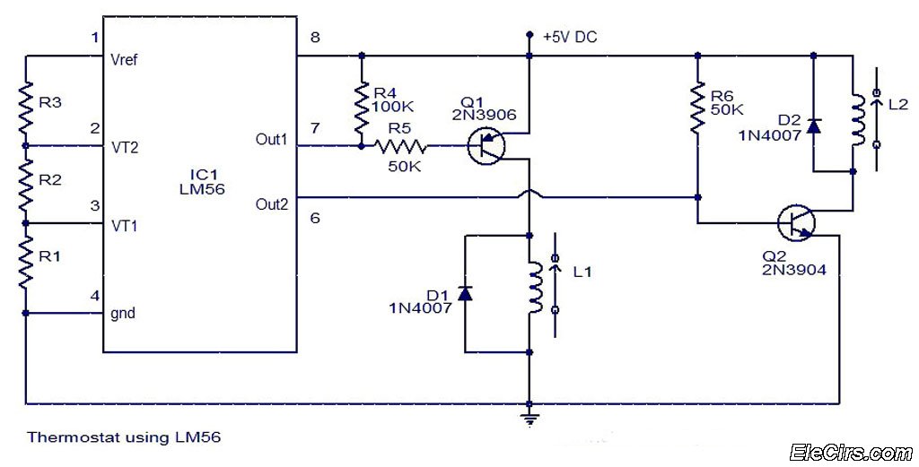
The LM56 Thermostat Project Circuit Diagram includes a schematic for the LM56 thermostat. The values of resistors R1, R2, and R3, which determine the required trip points VT1 and VT2, can be calculated using the following equations: VT1 =...
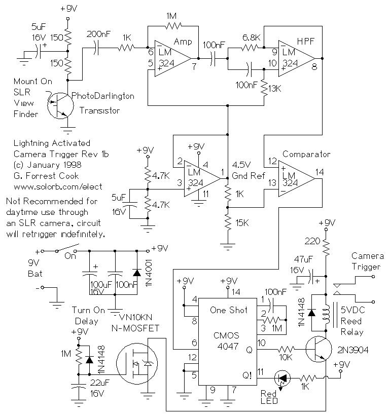
Basic information on the construction of various types of lasers from scratch, including topics such as home-built laser safety, setting up a home laser lab, sources of supplies and chemicals, vacuum systems, glass working, structural materials, power supplies, and...
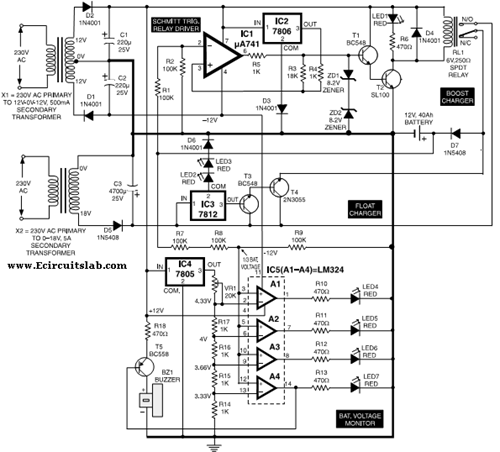
This circuit illustrates the use of the 7806 IC in an automatic battery charger circuit diagram. It is designed for a car battery with an approximate rating of 40 Ah. The automatic battery charger circuit utilizing the 7806 integrated circuit...
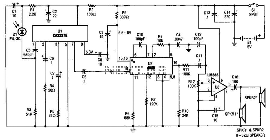
The infrared (IR) detector diode D1 captures the IR signal at approximately 40 kHz and transmits it to U1, a high-gain preamplifier, which then sends the signal to U2, a 4046 phase-locked loop (PLL) configured as a frequency modulation...
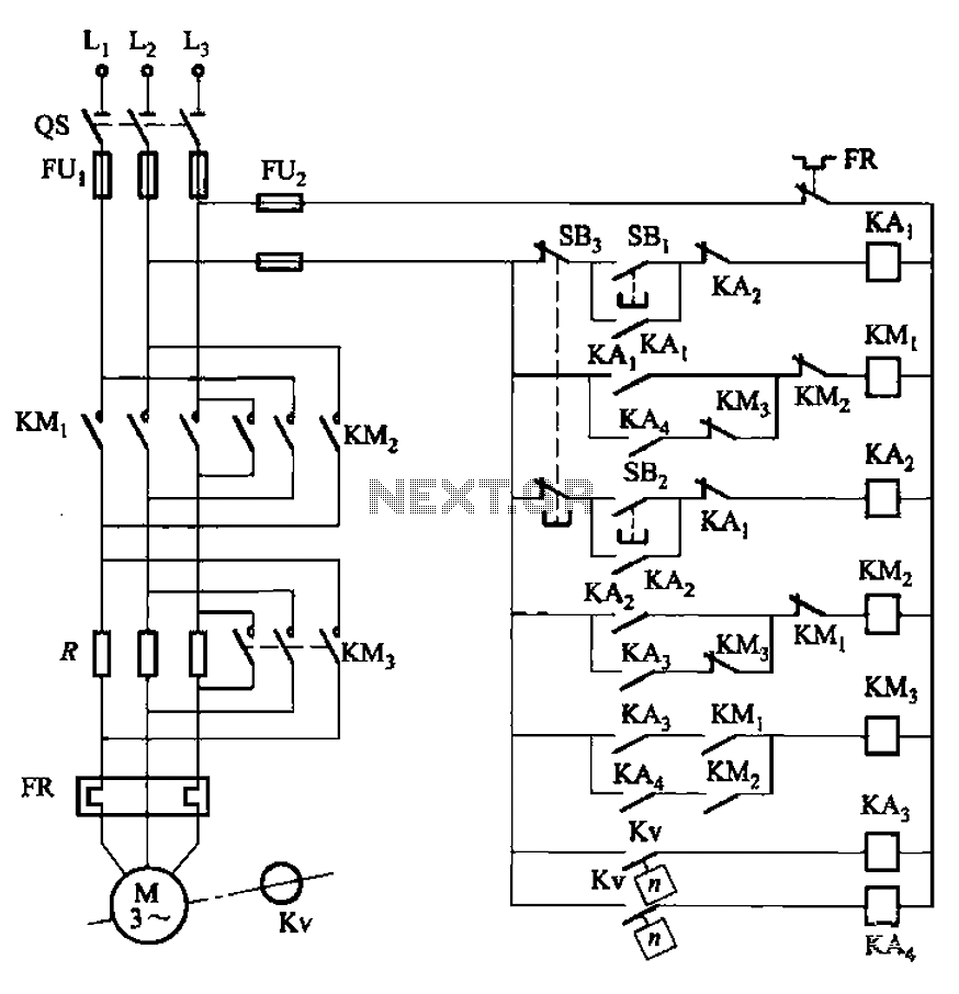
The circuit illustrated in Figure 3-130 differs from the circuit in Figure 3-129 in that when the stop button SB3 is pressed, the electric motor initiates braking. Furthermore, during both the startup and braking phases, the motor power lines...
A new high-performance regenerative receiver is available as a kit. The inclusion of an innovative regenerative detector circuit enhances sensitivity and overall performance. The regenerative receiver kit is designed to provide users with a high-quality radio frequency (RF) reception experience....