
Automatic Switch Project

The proposed controller system is designed to efficiently manage the operation of multiple trains on two distinct loops, enhancing both functionality and user experience. The integration of optical sensors allows for precise train detection and positioning, enabling seamless transitions between the inner and outer loops. The use of infrared technology ensures reliable operation, as the modulation at 38 kHz minimizes false triggering, thereby maintaining the integrity of the control system.
Block control mechanisms, primarily utilizing relays, will ensure that trains can be halted safely and effectively. The potential incorporation of diodes for gradual deceleration presents an opportunity to improve the overall user experience, making train stops smoother and more controlled. The alternative option of utilizing a microcontroller for power management introduces a higher level of sophistication, allowing for fine-tuned acceleration and deceleration profiles, although this approach may increase system complexity and cost.
Switch control will be adaptable, with the choice of electronic components to be finalized after testing various configurations. This flexibility ensures that the system can be tailored to meet specific operational requirements while maintaining reliability. The inclusion of manual and controlled sidings in the outer loop allows for versatile train operations, accommodating varying scenarios without compromising safety or efficiency.
The overall architecture of the control system will be depicted in the schematic, which will serve as a reference for implementing the necessary components and connections. The requirement for track insulators at the siding entrances ensures that trains can be effectively managed as they transition between powered and unpowered sections, further enhancing the operational reliability of the layout. Power sourcing for the switches and control systems will be carefully planned to ensure uninterrupted functionality, contributing to the overall success of the project.The objective of this controller project is to have automatic block and switch control of five separate engines that run on two completely independent loops of track. Part of each loop is outside (public) and part is inside (hidden from public view). The inside part has switch controlled sidings where the idle trains wait. The inner loop can accom modate three trains and the outer two trains. When a train completes its outside run and enters the inside area it is automatically assigned to an empty siding. It enters the siding and, when it reaches an optical sensor, power is removed from that block. One of the idle trains is activated and moves onto the outside area of the layout. The first drawing below shows the outside (public) part of the layout. Note that it will be revised to show two loops with one inside of the other, not one above the other as it is now depicted.
All trains will go through the two loops in a counter clockwise direction, entering at either "one-in" or "two-in". This means that control is only needed for switches 1, 4, and 6. Switches 1 and 4 control the inner loop and switch 6 controls the outer loop. Optical position sensors are installed at the points on the track labeled a, b, c, d, and e. The sections of track between a controlled switch and an optical sensor (between switch 4 and sensor a for example) are isolated from the main track power and make up a block where power can be removed so that the train stops and waits there.
5 Optical Sensors - These are made up of an infrared LED that is placed on one side of the track and an IR detector that is placed across from it. When the train breaks the IR beam a data pulse is generated. The IR LEDs are modulated at 38 kHz to prevent false readings. The IR detector (part #PNA4602M) only reacts to IR at this frequency. 5 block controls - These are likely to be relays that will completely remove power from a block when occupancy is detected.
This will bring the train to a sudden stop. To make the stop more gradual a series of diodes can be inserted in the track sections in the block to more gradually slow the train. The other option is to use a separate microcontroller to provide power to each block. This would allow complete acceleration / deceleration control but would add significantly to the cost and complexity of the system.
5 Switch controls - The microcontrollers will activate switches based on the position of the trains. The exact electronics to be used will be determined after some experimentation. Options include: relays, four Mosfets or Darlington transistors per switch, or one sn754410ne per switch The outer loop (labeled "one-in" through "one-out" in the second drawing) is made up of a manual siding (controlled by switch 3) and two sidings controlled by switch 6. Both blocks are unpowered. When the microcontroller system is activated track power, which is controlled by an independent radio controlled system, is activated so that the train on 6d can be operated.
This train moves out of the siding and exits on "one-out" All three blocks are unpowered. When the microcontroller system is activated track power, which is controlled by an independent radio controlled system, is activated so that the train on 4a can be operated. This train moves out of the siding and exits on "two-out" The schematic below (click the thumbnail to see the full sized image) shows the system that will control one of the loops.
A similar unit will control the second loop. Both units will be able to control three sidings by observing the status of three optical sensors and controlling two switches. Track insulators will need to be installed at both ends of each of the sidings where trains will be waiting to move into the public part of the layout.
there are two on the outside loop and three on the inside loop. Power will need to be supplied from an independent source to control the switches and to power the electr 🔗 External reference
Related Circuits
Designing a wide-range variable power supply using a linear regulator is straightforward; however, it suffers from poor efficiency when regulating a constant 60-volt source. A wide-range variable power supply can be implemented using a linear regulator, which allows for adjustable...
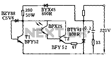
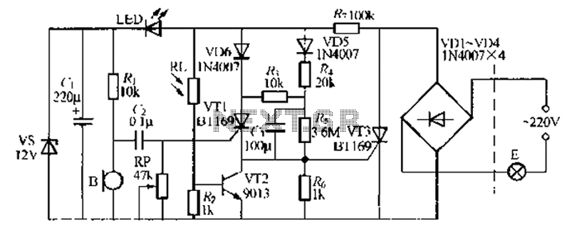
The circuit is designed to activate when the light intensity exceeds 700lx. In this configuration, a phototransistor and the BFY52 transistor are used to trigger the BTY91 thyristor with a current. When light strikes the phototransistor, a positive trigger...
This electronic circuit utilizes a 555 timer as the foundation for a touch switch. When the plate is touched, the 555 timer is activated, causing the output on pin 3 to go high, which turns on the LED and...
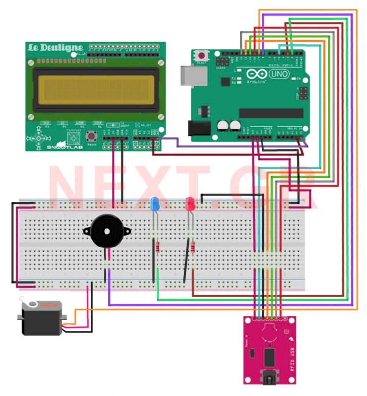
This project aims to develop a security system suitable for business environments or for simple home use. The system utilizes an Arduino Uno microcontroller in conjunction with RFID (Radio Frequency Identification) technology, enabling wireless user identification. Only registered users...
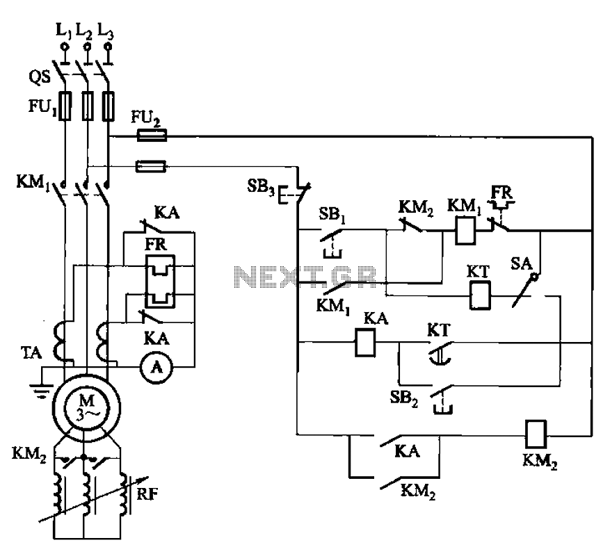
The circuit shown in Figure 3-164 can operate in both manual and automatic modes. During startup, the normally closed contact of relay KA is shorted, which affects the heating element to avoid prolonged startup times that could lead to...
A relatively simple circuit for controlling a stair walkway light with a delay feature. The circuit has a drawback in that the voice activation is somewhat less sensitive, making it sometimes difficult to trigger with general conversation. However, it...