
Automatic tape recording

The described circuit serves as an automatic tape recorder activation system designed for amateur radio operators. It utilizes the principle of squelch detection, which is a common feature in radio receivers that suppresses background noise when no signal is present. When the receiver detects a signal strong enough to break the squelch, it sends a control signal to the tape recorder, activating it to begin recording.
The circuit typically includes a comparator or a transistor switch that monitors the output of the receiver. When the audio signal exceeds a predetermined threshold, the comparator triggers the tape recorder. This activation mechanism ensures that only relevant audio is captured, reducing unnecessary recording of silence or noise.
To manage the shutdown of the recorder, a timing circuit is integrated, which often consists of a resistor-capacitor (RC) network. This network introduces a slight delay before the recorder turns off after the signal is lost. The delay allows the operator to capture any trailing audio that may occur after the initial signal has ceased, ensuring that important communications are not missed.
Overall, this circuit enhances the functionality of amateur radio setups, allowing operators to engage in activities away from their rigs without losing important transmissions. The design can be further optimized through the selection of components to tailor the sensitivity of the squelch detection and the duration of the delay, depending on the specific requirements of the user.Amateurs don"t have to miss the action while away from the rig. This circuit turns on a tape recorder whenever the receiver"s squelch is broken After signal loss, the recorder will shut off following a slight delay,.
Related Circuits
To achieve optimal audio reproduction across various listening levels, it is essential to adjust tone control settings to accommodate the known characteristics of human hearing. Human ear sensitivity changes in a non-linear fashion throughout the audible frequency range, as...

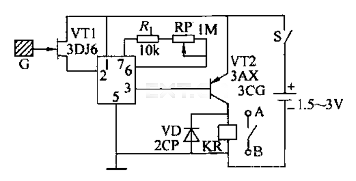
The circuit utilizes the Trigger and Threshold pins (2 and 6) to monitor maximum and minimum voltage levels. Two voltage comparator operational amplifiers within the 555 timer manage the output state, switching it on or off. The Trigger pin...
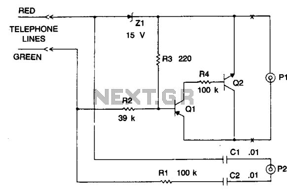
The device is a DC switch that remains normally on due to the forward biasing of Q1 through resistor R3. Q1 clamps Q2 into a forward state by biasing its complementary transistor well into saturation via resistor R4. The...
This circuit is a constant current protection type that limits the output current to a specific value in cases of over-current and short-circuit conditions. When the output current exceeds this limit, the output voltage decreases. The CW200 power management...
Model railroad turnouts, often referred to as switches, can be controlled in various ways. The simplest method is manual control, operated by hand. Remote activation is typically achieved through pneumatic (air) or electrical means. The project discussed in these...
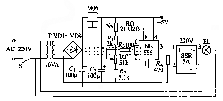
The NE555 time base circuit with an AC solid-state relay (SSR) can function as an automatic light switch circuit. The circuit diagram illustrates that during the day, the incandescent light is turned off due to the influence of the...