
Automatic Switch Project

The operation of model railroad turnouts is crucial for the seamless functioning of model railways. The various methods of control—manual, pneumatic, and electrical—provide flexibility in operation. The integration of microcontrollers allows for advanced automation in controlling multiple turnouts, enhancing the realism and complexity of model railroads. The use of transistors as intermediates is essential for handling the high current demands of turnout motors while protecting the microcontroller from potential damage due to excessive current draw.
When selecting turnout motors, it is important to consider their operational characteristics. The LGB 12010 and AristoCraft 11299 motors exemplify different approaches to turnout actuation. The LGB motor's rotating solenoid design offers simplicity and reliability, while the AristoCraft's gear-driven motor provides a unique power management feature that minimizes power consumption once the turnout is thrown. The Circuitron Tortoise, although lacking the power disconnection feature, offers a robust alternative with a design that accommodates continuous power draw without adverse effects.
For model railroad enthusiasts, understanding the intricacies of these motors and their control mechanisms is essential for effective layout design and operation. Proper wiring, including the use of diodes and SPDT switches, ensures reliable performance and ease of control. The careful selection and integration of these components can significantly enhance the functionality and enjoyment of model railroading.Model railroad turnouts, often called switches, can be controlled in a number of ways. The most basic is a manual control that is thrown by hand. Remote activation is usually accomplished by either pneumatic (air) or electrical means. The project that is the focus of these articles has several turnouts that must be remotely activated by a microcontroller. As mentioned in the last article the output power available on a PICAXE is quite limited, certainly nowhere near what is required to throw a turnout. I have seen many turnout motors drawing nearly 2 amps when activated so some sort of intermediate device, like the transistor that was used with the relays, is needed.
Before we can choose the appropriate device to operate the turnout we need to examine how turnout motors operate. The two most common electrically operated turnout motors utilized in garden railways are those made by LGB (item number 12010).
We will also examine a slightly less common unit from Circuitron called the slow motion Tortoise. Although not designed specifically for garden railway use it can easily be attached to most turnouts. In the photo below the five screws that hold the sides of its case together have been partially removed.
Oops - guess I voided the warranty! All three of the turnout motors operate in much the same way. Power goes to each turnout motor through two wires. When power is applied in one direction, that is the positive connection goes to one terminal while the negative goes to the other, the turnout is turned one way. When the polarity is reversed the turnout is activated in the other direction. The design of the AristoCraft 11299 utilizes a small DC motor to throw the turnout. The small motor`s power is multiplied by a set of gears. The most unique characteristic of the AristoCraft units is the inclusion of a set of contacts and a pair of diodes that completely disconnects the motor from power once the turnout has been thrown.
This means that the motor draws virtually no power once it is thrown and the power can be left on indefinitely. In the second photo the arm has been removed and turned over. The contacts on the bottom of the arm slide along the metal traces on the circuit board to disconnect the power from the motor once the turnout is fully thrown.
The two diodes, just to the left of the motor gears, reenergize the motor when the polarity of the DC power is switched. This close-up view shows the five contact screws. The two on the right are used to power the turnout motor. The three on the left make up the SPDT switch contacts with the center screw, marked "C", being the common terminal.
In the photo above you can follow the traces inside of the motor and see where they go. LGB `s 12010 utilizes more of a rotating solenoid actuator rather than a normal motor. When power is applied in one direction a permanent magnet rotates inside of a coil of wire throwing the control arm in one direction. When the polarity is reversed it rotates in the opposite direction, throwing the control arm the other way.
If power is left on the turnout motor will continue to draw current and will heat up. This does not seem to do any damage and only wastes power. Here the motor has been completely disassembled revealing the coil and the iron core that goes through it. Below the coil is the permanent magnet that normally sits between the sides of the iron core. The plastic pieces next to the magnet encase it and hold it centered in the unit. The LGB unit does not normally have switch contacts available but there is an add-on DPDT switch module (12070) that can be hooked to the end of the switch motor.
The Circuitron Tortoise`s motor is like the AristoCraft`s but it does not disconnect itself from power once the control arm moves. It simply stalls and continues to draw power as long as the circuit is complete. Again, this seems to be part of the design and appears to do no harm. The most sig 🔗 External reference
Related Circuits
This circuit is designed for a project utilizing a 6V, 400 mA DC power supply. The open-circuit voltage is specified, indicating the voltage measured when no load is connected. The circuit employs a regulated 6V power supply, which is essential...
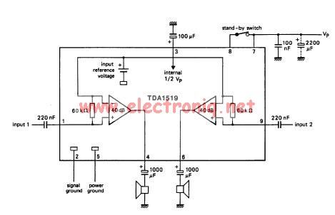
The TDA1519 circuit can deliver 2x6 watts output power. TDA1519 is an integrated class-B dual output amplifier in a 9-lead single in-line (SIL) plastic medium power package primarily developed for car radio applications. The TDA1519 is a robust integrated circuit...

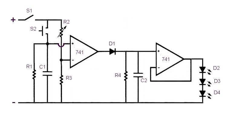
A simple yet accurate automatic regulated 6/12/24 volt lead-acid battery charger circuit is explained in this article. The circuit switches off the current to the battery as soon as the battery reaches full charge. An illuminated LED at the...
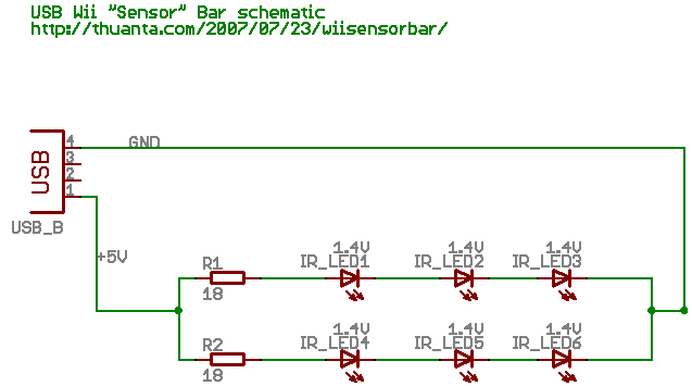
The following circuit illustrates the Wii "Sensor" Bar Project Circuit Diagram. Features include a series of infrared LEDs positioned at both ends of the bar, which emit infrared light. The Wii Sensor Bar is a crucial component for the Wii...
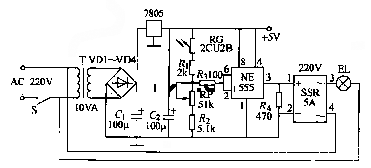
The NE555 time base circuit with an AC solid-state relay (SSR) can function as an automatic light switch circuit. The circuit diagram illustrates that during the day, the incandescent light is turned off due to the influence of the...
This sensitive sound operated switch can be used with a dynamic microphone insert as above, or be used with an electret (ECM) microphone. If an ECM is used then R1 (shown dotted) will need to be included. A suitable...