
Induction automatic switch circuit

The constant current protection circuit is essential in safeguarding electronic systems from damage due to excessive current conditions. The design effectively utilizes a combination of components to ensure that the output current remains within safe limits during fault conditions. The Zener diode plays a critical role in voltage regulation by providing a stable reference voltage, which is crucial for the operation of the transistor VT1. When the output current exceeds the threshold, the sensing resistor R detects this increase and triggers the conduction of VT1, thereby limiting the output current and protecting downstream components.
The configuration of the resistors RP2 and RP3 allows for precise adjustments to the circuit's performance. RP2 is particularly important for setting the maximum allowable output current, while RP3 adjusts the rate at which the output voltage decreases during overcurrent conditions. This flexibility ensures that the circuit can be tailored to meet the specific requirements of various applications.
Thermal management is another critical aspect of the circuit design. The CW200 regulator must be equipped with an adequately sized heat sink to dissipate the heat generated during operation, especially under high load conditions. The heat sink must be selected based on the expected power dissipation, which involves calculating the difference between the input voltage and the output voltage multiplied by the output current. This calculation ensures that the temperature of the regulator remains within safe operating limits, thereby enhancing the reliability and longevity of the circuit.
Finally, the inclusion of input and output capacitors is vital to stabilize the circuit and prevent oscillations that could lead to erratic behavior. Careful selection of these capacitors, considering their equivalent series resistance (ESR) and capacitance values, contributes significantly to the overall stability and performance of the constant current protection circuit.Constant current protection circuit type, since the over-current and short-circuit, the output current is limited only to a certain value, the output voltage drops, the overcur rent room a little longer, power management and power CW200 is still possible due to excessive damage. Shown for the reduced flow high current regulator 12-44. It lies in the use of Zener diode vs impact on VT1: When the amount exceeds the value of the output current flows through the sensing resistor R., The protective crystal tube VT1 conduction, the circuit into a constant-current protection status.
When the output voltage drops to the implicit value of the pressure regulator diode vs UD time (10V) or less, vs by VD2, RP3, RP2 to the base of VT1 injection current causes the output voltage Uo into a further decline, vs will be maintained in CW200 protection status main factor, R. Pressure drop becomes a secondary factor, which played a protection device and power tube effect. Circuit RP2 to micro adjust the current limit, RP3 used to adjust the degree of reduction processes. A brief review of the integrated regulator CW200 three basic usage. When using this regulator, should pay attention to add enough wattage large heat sink, a heat sink in accordance with Pw Jo (U, - soul) estimate, where L is the output current, U; the input voltage, U is value of the output voltage t goblets -UO to 5-8v appropriate.
When using the regulator input and output capacitor must eliminate vibration with no sense of capacitors.
Related Circuits
This is a circuit design for a temperature relay that can be used to signal a fire or monitor temperature set points. The adjustment of P1 is necessary to ensure that the base voltage of T1 is 0.5V lower...
A simple function generator that produces a specific frequency. While awaiting the arrival of the AD9832 chip, a basic version of a Direct Digital Synthesis (DDS) synthesizer was developed using only the AT2313 microcontroller and a resistor network. This...
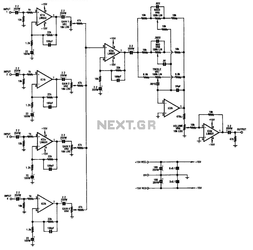
IC1-a, IC1-b, IC2-a, and IC2-b all operate with a gain of approximately 19. Their outputs are combined through level-control potentiometers, and the resulting signal is amplified by IC3-a before being sent to the tone-control stage IC3-b. Finally, the output...
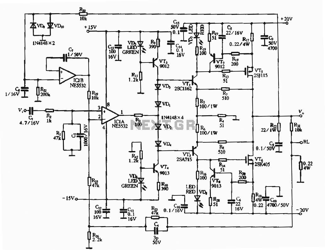
The circuit utilizes an FET amplifier configuration for output, incorporating an NE5532 operational amplifier powered by a 15V supply. The output stage features a FET that amplifies the voltage after passing through several stages. The bias circuit for the...
The simple audio mixer circuit is built on the common base principle, where input voltages are transformed into alternating currents which are summed to form the output. The simple audio mixer circuit utilizes a common base configuration to achieve effective...

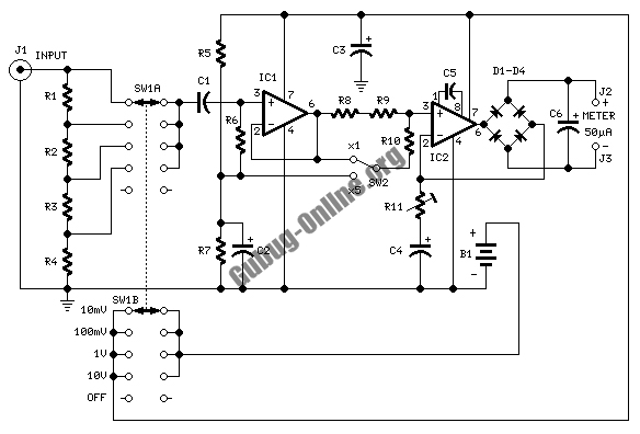
A VU (Volume Unit) meter has traditionally been a key component of audio metering systems. The Peak Program Meter (PPM) is known for its inadequacy in accurately displaying peak signal levels. This circuit serves the same function as previously...