
Automatic telephone call recording circuit

The described circuit operates by utilizing the DC voltage levels present on a telephone line to control a relay. The relay serves as a switch that activates a step-down converter, which reduces the high voltage from the telephone line to a lower, manageable level suitable for powering additional devices, such as a tape recorder.
When the telephone is in the on-hook state, the line voltage remains high, typically between 45 to 50 volts. In this state, the relay is deactivated, preventing any current flow to the tape recorder. Once the telephone is taken off-hook, the voltage drops to around 6 volts, which activates the relay. This transition is crucial as it signals the system to switch from standby mode to operational mode.
The relay, upon activation, connects the tape recorder to the audio input from the telephone line. The audio signal, which can be derived from the microphone or directly from the telephone line, is then processed and recorded by the tape recorder. This setup allows for efficient recording of conversations or audio signals transmitted over the phone line.
The circuit design may include additional components such as diodes for protection against voltage spikes, capacitors for filtering noise, and resistors to limit current where necessary. Properly sizing these components is essential to ensure reliable operation and to prevent damage to the tape recorder or other connected devices. The overall schematic should allow for easy integration with existing telephone systems while maintaining compliance with safety standards.DC voltage present on the telephone line is usually about 45 to 50V, on-hook and off-hook to 6V. The step-down circuit relay is activated. Relay control tape recorder. Audio is input through the network to tape the microphone.
Related Circuits
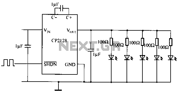
The CP2128 is a low-noise, fixed-frequency step-up DC/DC converter designed for garden applications. It operates within an input voltage range of 2.7V to 4.5V and can generate a stable output voltage of 5V, with a maximum output current of...
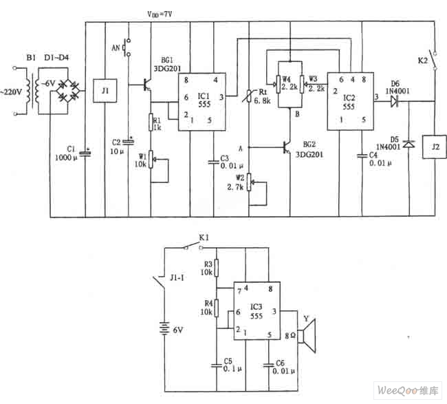
The figure illustrates the automatic watering control circuit for bean sprouts. The controller includes a step-down rectifier circuit, a power outage detection component (IC3), a timing control circuit (IC1), and a temperature control circuit (IC2). The step-down rectifier circuit...
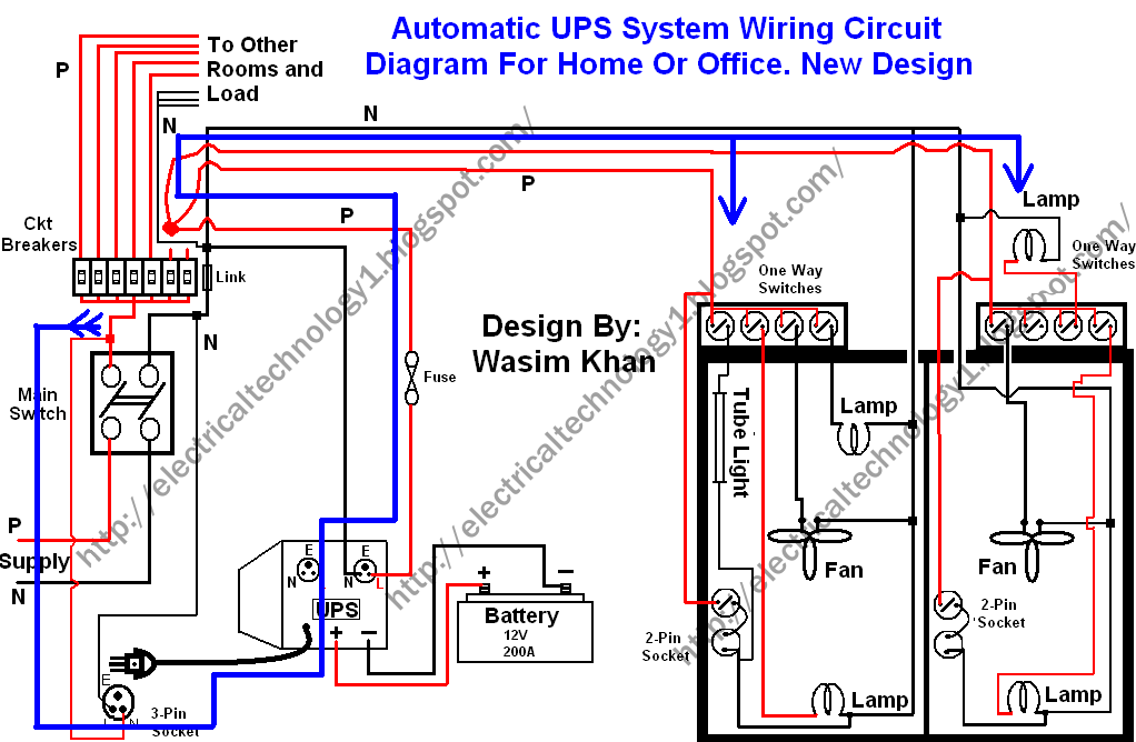
This wiring circuit diagram is designed for providing power to specific rooms in a home or office during a power supply failure. It ensures continuous power supply to devices such as laptops and computers in those particular rooms, especially...
This circuit is a digital panel meter (DPM) featuring an analog bar graph display and a 3.5-digit digital display. The ICL7107 is configured for 200mV input. The U4A operational amplifier (LF353) amplifies the 200mV full-scale input to the required...
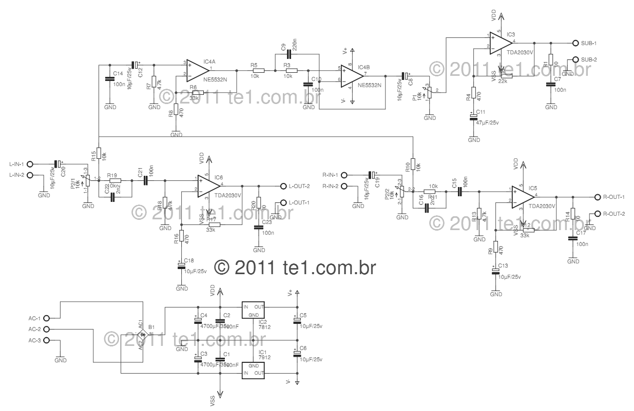
This circuit is a complete application for a 2.1 amplifier system, consisting of two satellite speakers powered by a TDA2030 and one subwoofer. This 2.1 system is commonly utilized in commercial applications as an amplifier for computers, enhancing audio...
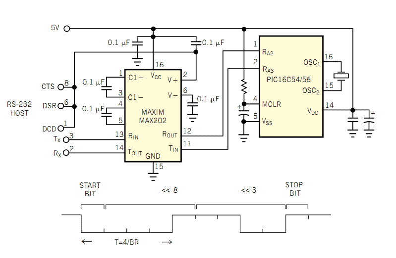
The popularity and easy access of RS-232 ports lend them to many communication projects. You can use a port as is or as a tiny parallel port when the exchange uses only control lines. Before the asynchronous serial-data transfer...