
Automatic UPS system wiring circuit diagram for Home or Office (New Design With One Live Wire)
")
The described circuit involves a configuration where both the phase and neutral wires are initially connected from the power source to various electrical appliances. The integration of a UPS (Uninterruptible Power Supply) into this circuit allows for seamless transition between the main power supply and battery backup during power outages.
In this setup, the UPS is responsible for charging the batteries while simultaneously supplying power to the appliances. The phase wire from the UPS is connected to the same point as the phase wire from the power source, ensuring that appliances receive power from either the UPS or the main supply as needed. The neutral wire remains connected to the appliances, allowing for the completion of the circuit.
When the main power supply is active, the UPS remains in standby mode, and the appliances draw power directly from the main source. However, in the event of a power outage, the UPS automatically switches to battery power, allowing the appliances to continue operating without interruption. It is crucial to note that the second phase wire connected after the UPS installation remains inactive during normal operation, as the UPS is not drawing power from the batteries until the main supply fails.
The design ensures that the stored electrical energy in the batteries is utilized effectively when the main power supply is unavailable. This configuration enhances the reliability of the electrical system, providing continuous power to essential appliances while maintaining safety and efficiency. Proper installation and adherence to electrical codes are essential to ensure the system operates as intended and to prevent potential hazards.We had already connected Phase & Neutral (from Power house) to Electrical Appliances i. e. Fans, Light points etc. So according the above UPS Connection Diagram. connect an extra wire (phase) to those appliances where we have already connected phase and neutral from (from Power house) (i. e. , two wire as phase with same point). So no need to connect Neutral from UPS as it is already connected. Then Supply will continue through Phase wire (Note that Neutral is already connected) which is given to UPS from main board (it will charge your battery as well). and then from UPS to Electrical Appliances. So the Second one phase which is connected after UPS installation (i. e. One Live Wire from UPS) would be inactive because power supply is not available from UPS and batteries (Because it is Automatic UPS System).
then Supply will continue through Phase wire (Output UPS) which is Connected from batteries and UPS to Appliances (Note that Neutral is already connected). So the first one phase which is connected before UPS installation (i. e. Live Wire from Main board to UPS) would be inactive because power supply is not available from power house.
In this case, you consume the store Electrical energy in the batteries. 🔗 External reference
Related Circuits
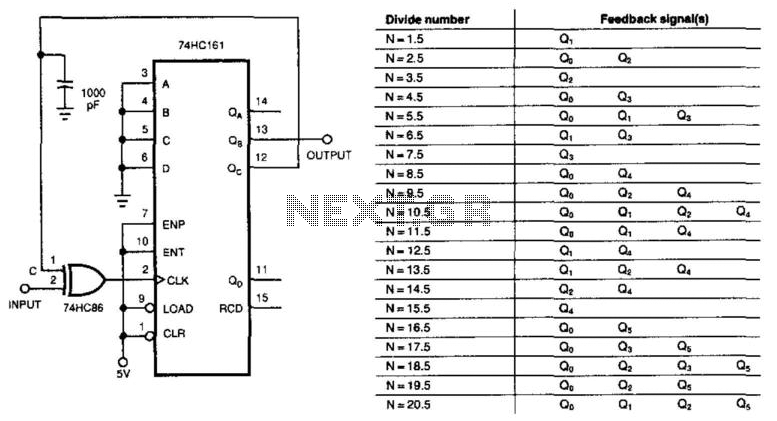
This circuit divides the input signal by +1/2 instead of dividing by an integer. With the feedback connections as illustrated in the figure, the circuit effectively divides by 3.5. Point C ultimately determines when the input triggers the 74HC161...
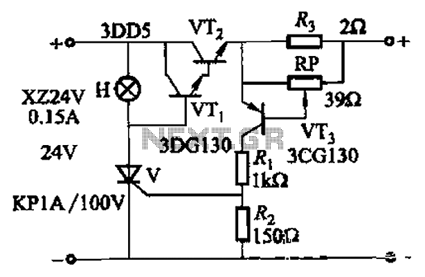
By adjusting Ro or RP, the current setpoint can be modified. The circuit illustrated in Figure 14-98 features overcurrent protection using a thyristor and transistors VTi and VT2, which immediately cut off the power when an overcurrent condition is...
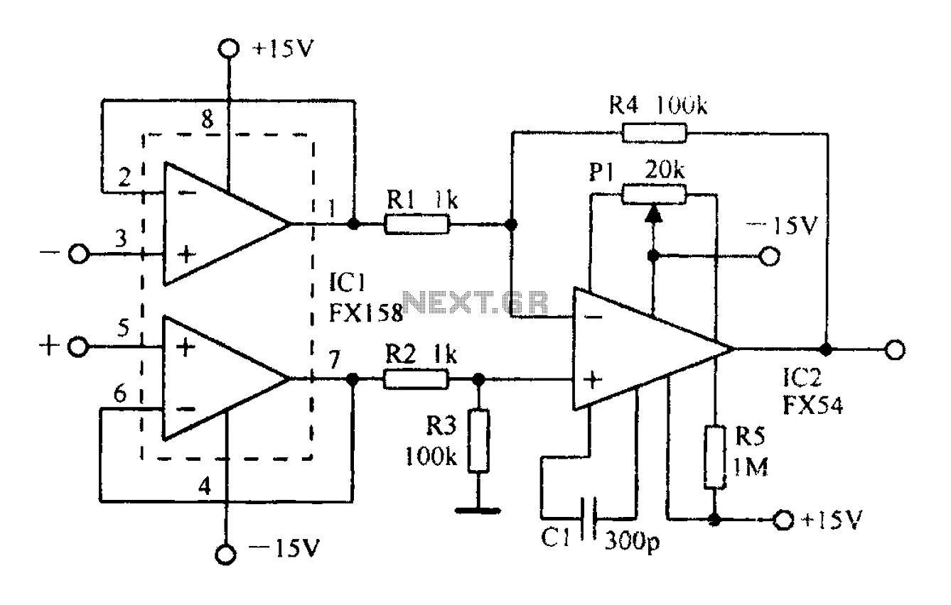
A differential amplifier with input impedance as indicated in the circuit diagram. A differential amplifier is a crucial component in various electronic applications, primarily used to amplify the difference between two input voltages while rejecting any common-mode signals. This characteristic...
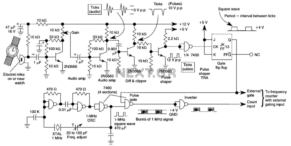
This circuit adapts a frequency counter to measure intervals. It was originally utilized as a shutter speed checker for photographic applications. The watch ticks are clipped, shaped, and formed into a square wave. This square wave is employed to...
This circuit is a small +5V power supply, which is useful when experimenting with digital electronics. Small inexpensive wall transformers with variable output voltage are available from any electronics shop and supermarket. Those transformers are easily available, but usually...

This is an infrared-based broken beam alarm designed to protect doors and entry passages. It emits a loud alarm when someone crosses the invisible infrared barrier. The infrared-based broken beam alarm system operates by utilizing a pair of infrared emitters...