
Thyristor overcurrent protection circuit 2

This circuit utilizes a thyristor for overcurrent protection, which is a crucial component in safeguarding electronic systems from damage due to excessive current. The thyristor operates by remaining in a conducting state until the current flowing through it falls below a certain threshold. In this configuration, transistors VTi and VT2 are employed to monitor the current level. When the current exceeds the predefined setpoint, the circuit triggers the thyristor to turn off, effectively disconnecting the load and preventing potential damage.
The inclusion of an adjustment potentiometer (RP) provides flexibility in setting the desired current threshold. This allows for customization based on the specific requirements of the application. The adjustment can be made by rotating the potentiometer, which modifies the resistance in the circuit, thus changing the voltage at the trigger input of the thyristor.
The indicator H serves as a visual alert, illuminating when an overcurrent condition has been detected. This feature is essential for operators to quickly identify issues within the system and take necessary actions to mitigate risks.
Overall, the circuit design emphasizes rapid response to overcurrent situations, ensuring that the electronic system remains protected while allowing for user-defined current settings through the adjustable potentiometer. The integration of these elements makes the circuit a reliable solution for managing current levels in various electronic applications.Adjusting Ro or RP, you can change over the current setpoint. Circuit shown in Figure 14-98. Overcurrent, V conduction thyristor, transistor VTi, VT2 off immediately cut off th e power play fast protection, the indicator H lights. Adjustment potentiometer RP, can change over the current setpoint.
Related Circuits
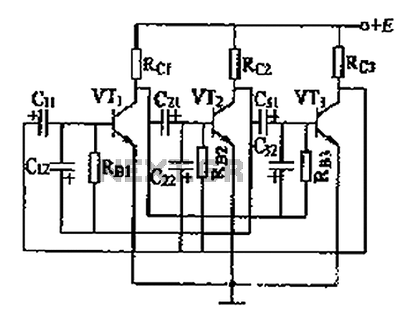
The three astable circuit is illustrated, demonstrating that each level of the transistor's base is connected by a capacitor between the two levels, ensuring tight coupling. Additionally, each base electrode is biased through a resistor (Rb) connected to the...
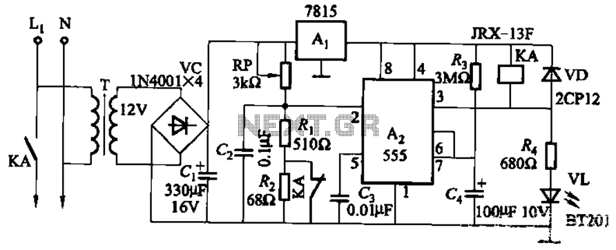
This circuit is applicable in refrigerators and other protective devices. It employs a 7815 three-terminal voltage regulator integrated circuit and an NE555 timer IC configured as a one-shot circuit for delay control. When the voltage drops below 180V, relay...
This infrared transmitter utilizes pulse width modulation (PWM). The transmitter is equipped with an LM567 tone decoder circuit. An audio signal (at least 50 mV peak-to-peak) is amplified with transistor T1 and subsequently used to modulate IC1. The frequency...
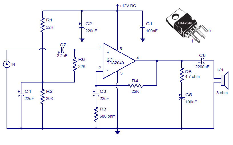
The Car Stereo Amplifier Circuit featuring the TDA2040 is presented here. The TDA2040 is a monolithic integrated audio amplifier that operates in Class AB mode. This integrated circuit includes built-in short circuit protection and thermal management features, allowing it...
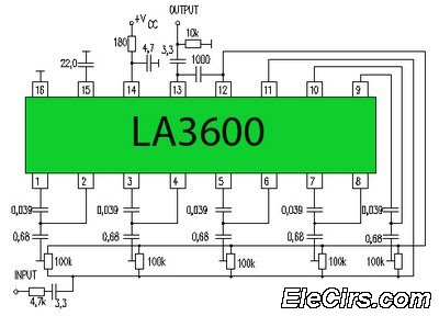
Circuit LA3600 5 Band Equalizer Circuit Schematics. One type of tone control in audio electronics is the graphic equalizer. Graphic equalizers can be categorized into two types: bar and other configurations. The LA3600 circuit is a 5-band graphic equalizer designed...
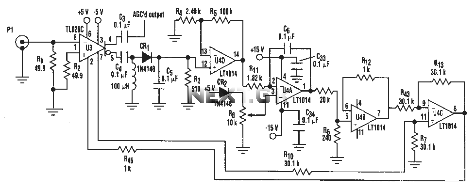
A simple IF AGC signal with a wide dynamic range and excellent linearity characteristics may be composed of two chips: the TL026C T1 voltage control amplifier IC and the LT1014 (or any other similar basic quad op amp device). The...