
Automatically disconnect the battery charger circuit

The circuit described involves a 500-ohm resistor that plays a crucial role in regulating the operation of a fully charged battery system. This resistor can be employed in various applications, such as voltage dividers, current limiting, or as a part of feedback loops in more complex circuits.
In a typical configuration, the 500-ohm resistor may be connected in series or parallel with other components, depending on the desired circuit behavior. For instance, when used in series with a load, it can help limit the current flowing through the circuit, thereby protecting sensitive components from excessive current. In scenarios where the resistor is placed in parallel, it can be used to create a voltage divider that provides a specific output voltage derived from the battery's total voltage.
The integration of this resistor into a fully charged battery circuit ensures that the system operates within safe parameters, maintaining the integrity of the battery and preventing over-discharge or over-current conditions. Furthermore, the resistor's value can be adjusted or replaced to modify the circuit's performance, allowing for flexibility in design.
In summary, the 500-ohm resistor is a vital component within a fully charged battery system, serving to regulate current and voltage, thereby enhancing the overall reliability and functionality of the circuit. By setting the 500 ohm resistor to adjust the circuit, the resistor is part of a fully charged battery.
Related Circuits
Very often when enjoying music or watching TV at high audio level, we may not be able to hear a telephone ring and thus miss an important incoming phone call. To overcome this situation, the circuit presented here can...
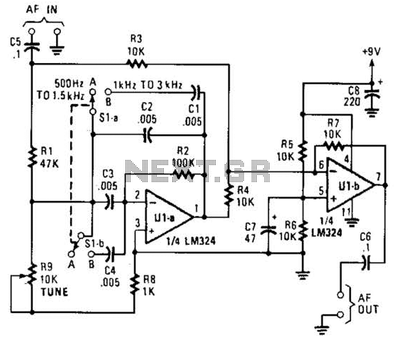
The notch filter can be integrated into nearly any receiver to attenuate a specific frequency by over 30 dB. This filter is particularly useful for diminishing heterodynes and whistles. A notch filter, also known as a band-stop filter, is designed...
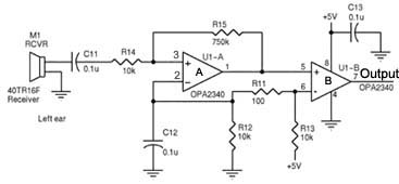
Assistance is required regarding the circuits provided below. The focus is on an ultrasonic receiver circuit that utilizes two ultrasonic components. The ultrasonic receiver circuit is designed to detect ultrasonic waves, typically in the frequency range of 20 kHz to...
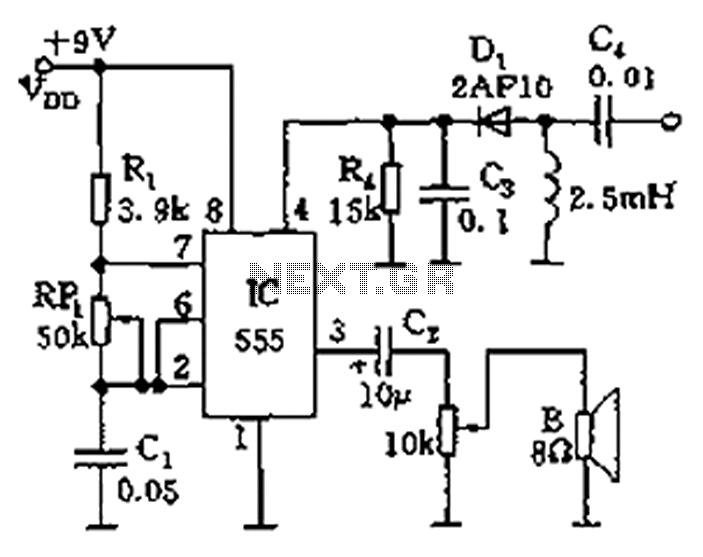
The circuit features a 555 timer integrated circuit along with components R1, RP1, C1, and others, which together form an audio oscillator. The frequency of the oscillator is determined by the formula f = 1.44 / ((R1 + 2...
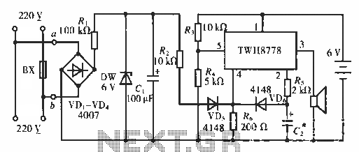
The circuit functions as an AC blown fuse alarm. When the fuse (BX) is intact, 220 V AC voltage passes through a bridge rectifier composed of diodes VD1 to VD4. Resistor R1 limits the current, and the output is...
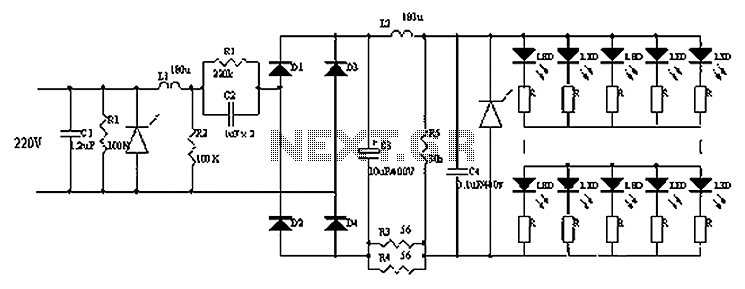
Circuits C1, R1, varistors, L1, and R2 form a filter circuit that includes a primary power supply capable of filtering out transient overvoltage inputs. The circuit also consists of C2 and R2, with additional components C3, C4, and L2....