
Phone line audio muting circuit

The circuit operates as a telephone ring indicator and audio muting system, providing a practical solution for missed calls during high audio activities. The core components include an opto-coupler (IC1), which detects the ringing signal from the telephone line. The opto-coupler's internal transistor activates when a ringing voltage is present, allowing current to flow through capacitor C1. This capacitor is critical for maintaining a charge that keeps transistor T1 in a forward-biased state, which in turn energizes the relays.
Relay RL1 is responsible for controlling a light bulb, providing a visual cue for an incoming call. Relay RL2 interrupts the audio path to the TV speakers, while relay RL3 mutes the music system speakers. The circuit design incorporates a diode (D1) to protect the opto-coupler from high voltage spikes commonly associated with ringing signals, ensuring safe operation.
The relays are configured to remain energized even after the initial ringing signal ceases, as long as the telephone handset is off-hook. This is facilitated by a low-impedance path through the cradle switch, which keeps the opto-coupler active. Once the call is completed and the handset is returned to the cradle, the relays are deactivated, restoring normal audio functions.
For installations involving dual speakers, a DPDT relay can be utilized to manage audio signals more effectively. The circuit is designed to provide both visual and audio management features, enhancing the user experience by ensuring that important calls are not missed during entertainment activities. Very often when enjoying music or watching TV at high audio level, we may not be able to hear a telephone ring and thus miss an important incoming phone call. To overcome this situation, the circuit presented here can be used. The circuit would automatically light a bulb on arrival of a telephone ring and simultaneously mute the music system/TV audio for the duration the telephone handset is off-hook.
Lighting of the bulb would not only indicate an incoming call but also help in locating the telephone during darkness. On arrival of a ring, or when the handset is off-hook, the inbuilt transistor of IC1 (opto-coupler) conducts and capacitor C1 gets charged and, in turn, transistor T1 gets forward biased.
As a result, transistor T1 conducts, causing energisation of relays RL1, RL2, and RL3. Diode D1 connected in anti-parallel to inbuilt diode of IC1, in shunt with resistor R1, provides an easy path for AC current and helps in limiting the voltage across inbuilt diode to a safe value during the ringing. (The RMS value of ring voltage lies between 70 and 90 volts RMS.) Capacitor C1 maintains necessary voltage for continuously forward biasing transistor T1 so that the relays are not energised during the negative half cycles and off-period of ring signal.
Once the handset is picked up, the relays will still remain energised because of low-impedance DC path available (via cradle switch and handset) for the in-built diode of IC1. After completion of call when handset is placed back on its cradle, the low-impedance path through handset is no more available and thus relays RL1 through RL3 are deactivated.
As shown in the figure, the energised relay RL1 switches on the light, while energisation of relay RL2 causes the path of TV speaker lead to be opened. (For dual-speaker TV, replace relay RL2 with a DPDT relay of 6V, 200 ohm.) Similarly, energisation of DPDT relay RL3 opens the leads going to the speakers and thus mutes both audio speakers.
Use NC contacts of relay RL3 in series with speakers of music system and NC contacts of RL2 in series with TV speaker. Use NO contact of relay RL1 in series with a bulb to get the visual indication. 🔗 External reference
Related Circuits
When this thermometer is utilized in a room environment, it operates intermittently, maintaining this operational state within the temperature measurement circuit due to the stable internal temperature. The astable multiresonance oscillator is composed of transistors VT1 and VT2, forming...
The south circuit consists of four parts, arranged in descending order: an NPN transistor dynamic garbage device (T1), a PNP transistor differential amplifier (T2, T3) forming a double differential circuit, two balanced output amplifiers with opposite phase, and a...
This is an efficient four-stage stabilized power supply unit designed for testing electronic circuits. It delivers well-regulated and stabilized outputs, which are crucial for achieving accurate results in most electronic applications. The circuit features an audio-visual indication system that...

This simple circuit drives six LEDs in a "Knightrider scanner mode." Power consumption primarily depends on the type of LEDs used, particularly when utilizing a 7555 (the CMOS version of the 555 timer). The circuit is designed to create a...
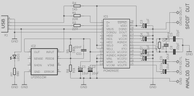
This is a high-quality preamplifier circuit with a built-in USB DAC designed for the Leachamp power amplifier. The schematic is derived from the PCM2902 datasheet. The circuit includes a DAC and ADC, SPDIF output and input, and an HID...
The circuit receives its input from the zero-crossing detector, which generates a 0-to-1-to-0 pulse to set the R-S flip-flop and activate the ramp circuit (A to Ramp) to initiate the timing ramp ascent. The described circuit operates by utilizing a...