
Stepper motor control circuit
The FD-CAS-923 stepper motor control experiment board is designed to facilitate experimentation with stepper motor operations, enabling users to explore the principles of digital control, speed regulation, and directional movement. The 4-phase stepper motor is characterized by its ability to achieve precise positioning and smooth motion, making it suitable for applications requiring accuracy. The integration with the EICE51 simulation interface allows for real-time monitoring and adjustments during experimentation.
The connection of the JK1 cop 40 core flat cable connector ensures reliable signal transmission between the control board and the stepper motor, minimizing potential interference. The dual power supply arrangement, with +5V from EICE51 and +12V from an external source, provides the necessary voltage levels for both logic and motor operation.
In the stepping motor drive circuit, the inclusion of current-limiting resistors (Rs to R8) is crucial for protecting the motor coils from excessive current, which could lead to overheating or damage. The flyback diodes (VD1 to VD4) are essential for managing back EMF generated during the motor's operation, ensuring that the circuit remains stable and preventing voltage spikes that could affect other components.
The transistors (VT1 to VT4) function as electronic switches, allowing for rapid control of the motor phases based on the pulse signals from the microcontroller. The use of a three-phase six-shot mode enhances the motor's performance by providing smoother transitions between steps, reducing vibrations and increasing efficiency.
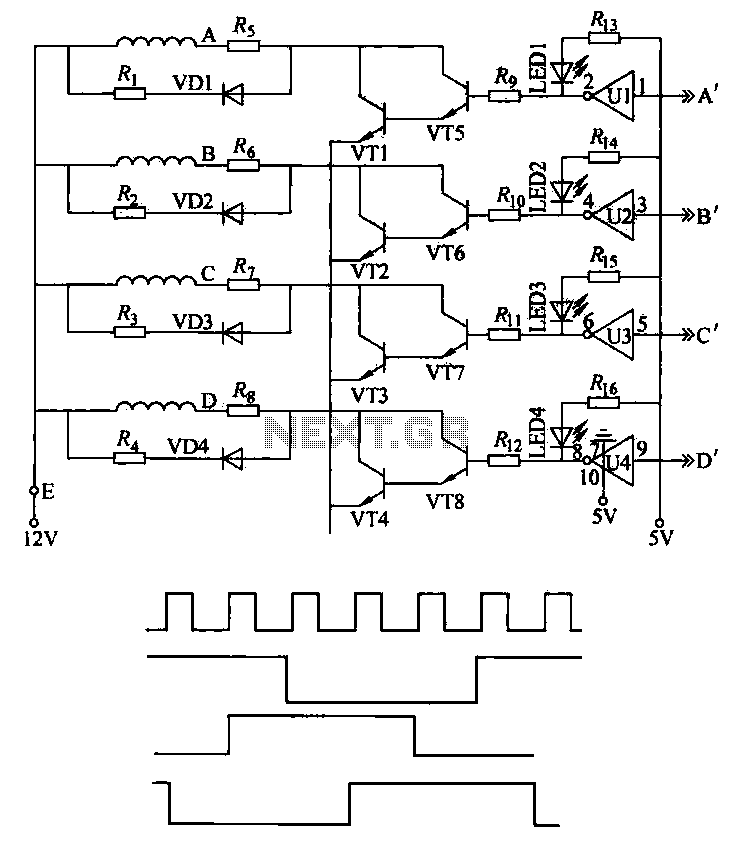
Overall, the design and implementation of the FD-CAS-923 stepper motor control experiment board exemplify a comprehensive approach to stepper motor control, integrating hardware and software components to achieve precise and reliable motor operation. This setup serves as an educational tool for understanding the complexities of stepper motor dynamics and control methodologies.This machine uses FD-CAS-923 1 stepper motor control experiment board with 4-phase step motor to avoid its schematic shown in Figure 4-42a, JK1 cop 40 core flat cable connector, the signal arrangement of EICE51 simulation compatible interfaces can be connected directly to EICEsl the artificial mouth. + 5v power supplied by EICE51, + 12V power plug through external rKl. 1) According to the working principle of a stepping motor, using 8031 Pl. 4-7 are respectively connected to the stepping motor driver A, B, C, D phase, software controlled pulse output port Pl sequence, control the stepper motor speed, direction, step distance. At the same time as the stepping motor rotation state can be observed in the A, B, C, D phase output installation status indicator.
2) stepping motor drive circuit Rs ~ R8 current limiting resistor to limit the current value of the coil, diode VD1 ~ VD4 crystal formation reflux coil current loop off the tube, also known as reflux diode, the choice should consider the supply voltage and the coil current. VT1 ~ VT4 as the switching transistor. Control process works as follows. Operation of the stepping motor is controlled by a pulse signal, the traditional method is to use digital logic circuits - ring pulse distributor control stepper motor stepper.
Figure 4-42b process control waveform. (1) running direction control stepper motor with a three-phase six shot mode, if press A - AB + BC-Ib, C + CA-energized II.A order to forward, if by A- AC -C-CB- B - BA - a sub- energize the reverse order. (z) to control the speed of operation from FIG. 4-42b can be seen that, when changing the CP pulse cycle time, ABC three-phase windings of high and low width will change, which leads to power and power variations caused by the rate of changes in the motor speed changes, so adjust the CP pulse cycle can be controlled step into the motor operating speed.
(3) Since the rotation angle of each of the input control pulse CP into a three-phase windings of the stepping motor changes state once, and accordingly a rotation angle degrees, so the angle of rotation of the stepping motor by the output pulse number is determined in the CP. The machine adopts 8031 controlled stepper electric motive operation, according to a three-phase six shot mode in Pl mouth out control code, make forward or reverse.
Because of this small change cycle output port Pl code control operation of the motor speed:
Related Circuits
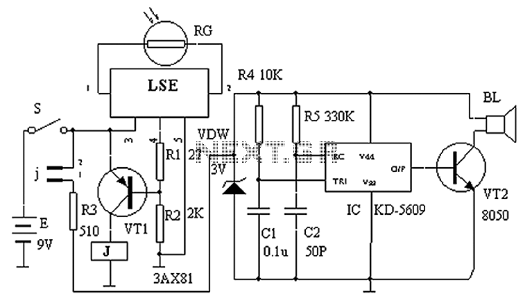
The circuit principle is illustrated in the accompanying figure. When the night light shines on the photosensitive resistor RG, it exhibits a high resistance (significantly greater than 50K). As a result, the output of the LSE pin is low,...
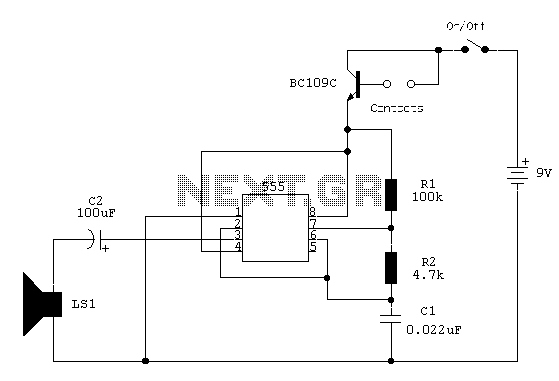
The circuit utilizes a 555 timer configured as an astable oscillator, powered by the emitter current of a BC109C transistor. In dry conditions, the transistor remains off due to the absence of bias current. However, when the probes become...
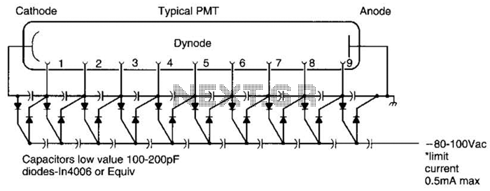
A Cockcroft-Walton voltage multiplier provides the necessary stepped voltage for the dynodes of the photomultiplier tube (PMT) without the use of a power-wasting voltage-divider resistor, which is typically employed in traditional configurations. The Cockcroft-Walton voltage multiplier is a type of DC-DC...
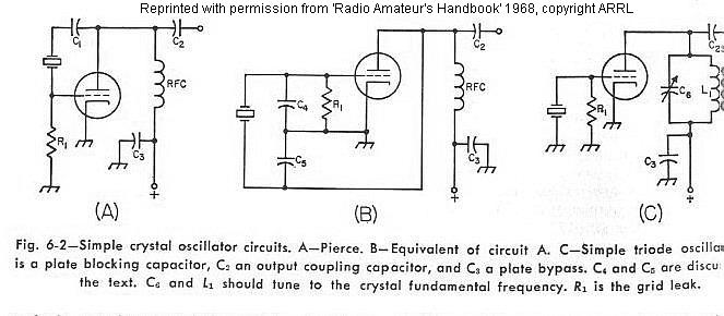
The frequency of a crystal-controlled oscillator is maintained with high precision through the use of a quartz crystal. The frequency is primarily determined by the dimensions of the crystal, particularly its thickness, while other circuit parameters have minimal impact....
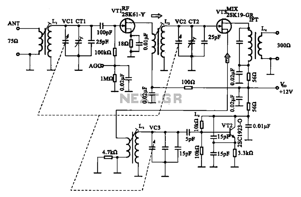
The FM radio circuit consists of a high-frequency amplifier (VT1), a mixer and local oscillator (VT2), and additional components. The circuit includes an FM radio antenna for signal detection, with an input transformer (L1) connected to a gate transistor...
Built around an LM380, this amplifier includes tone controls and electronic "soft switching". The soft switching circuitry ensures power is built up gradually eliminating the dc thump. The soft switching is enabled by a BD131 transistor wired as a...