
FM radio tuning circuit circuit
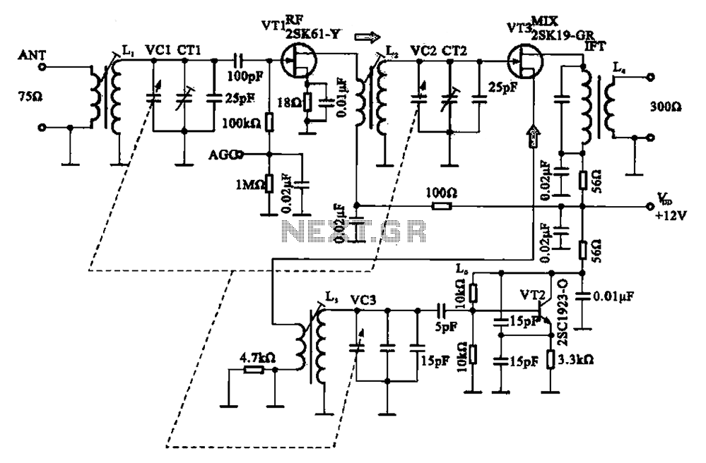
The FM radio circuit described operates by utilizing a combination of transistors and transformers to achieve effective signal amplification and mixing. The high-frequency amplifier (VT1) plays a crucial role in boosting the weak signals received by the antenna. The input transformer (L1) is essential for impedance matching and ensuring efficient signal transfer to the gate of the amplifier.
The local oscillator (VT2) generates a stable frequency that is mixed with the incoming FM signal in the mixer circuit (VT3). This mixing process produces an intermediate frequency (IF) signal, which simplifies further processing and demodulation. The resonant circuit configured with inductors and capacitors (LC) is pivotal in determining the local oscillator frequency, ensuring that it is properly tuned to the desired signal frequency.
The output from the mixer circuit is then passed through the intermediate frequency transformer (IFT or L4), which is tuned to 10.7 MHz, a common IF frequency for FM radio applications. This stage is critical for filtering and amplifying the mixed signal, allowing for better selectivity and sensitivity of the receiver.
Overall, this FM radio circuit exemplifies the fundamental principles of radio frequency engineering, incorporating various components to achieve robust performance in receiving and processing FM signals. Proper design and tuning of each component are essential for optimal operation and quality of reception in the final audio output.32.FM radio circuit ; FM radio tuning circuit circuit (2) FET circuit in FM radio application tuning circuit is shown in Figure FM radio circuit, which is composed of a high fr equency amplifier VT1, VT3 mixer and local oscillator VT2 and other parts of. FM radio antenna sensing signal, the input transformer Li added, rri gate transistor, VT1 high frequency discharge main amplifier device, after it amplifies the FM frequency signal transformer L2 is applied to the gate of the mixer circuit VT3 pole, yrl2 and LC resonant circuit configuration cost local oscillator, the oscillation signal from the oscillation transformer din secondary source sent to the mixer circuit VT3 pole. Mixer circuit VT3 output from the drain, the intermediate frequency transformer IFT (L4) 10.7 MHz IF output signal.
Related Circuits
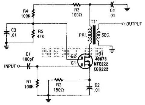
A MOSFET is utilized as a wideband buffer amplifier. T1 is wound on a toroid of approximately specified diameter, using material suitable for the frequency range, typically between 1 MHz and 20 MHz. The turns ratio should be approximately...
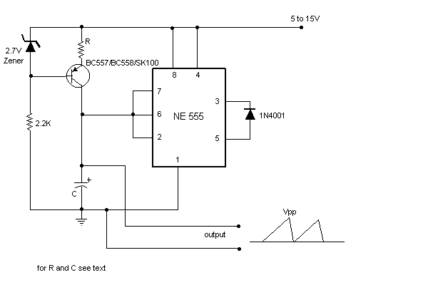
Sawtooth wave generators using opamp are very common. But the disadvantage is that it requires a bipolar power supply. A sawtooth wave generator can be built using a simple 555 timer IC and a transistor as shown in the...

Connect the components, ensuring to pay attention to the connections for the transistor. The 22-ohm load resistor and thermistor should be connected in a manner that allows for good thermal contact. Note: If using the Light Application Adapter, REFIN-...
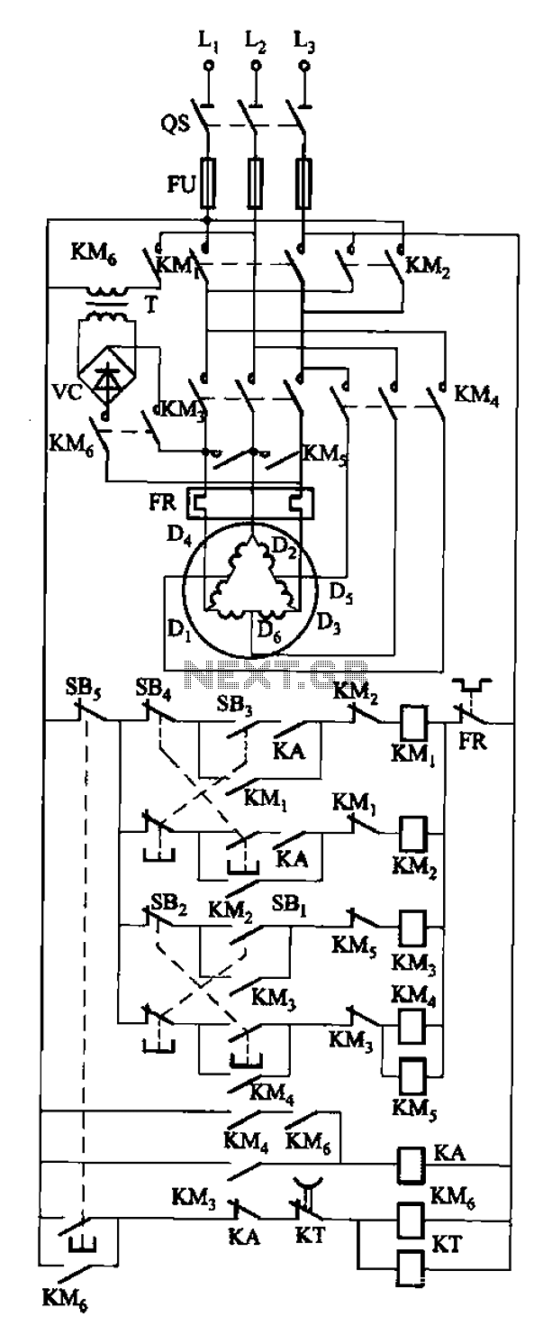
The circuit depicted in Figure 3-108 includes various control buttons: SB3 for the forward button, SI for the reverse button, SBi as the low start button, SB2 for the speed start button, and SBs for the stop button. KMs...
Over-Temperature Alarm Circuit Uses Common, Inexpensive Components | Negative-temperature-coefficient (NTC) thermistor, ICs. The Over-Temperature Alarm Circuit is designed to detect excessive temperatures and provide an alert using readily available and cost-effective components. The core sensing element of this circuit is...
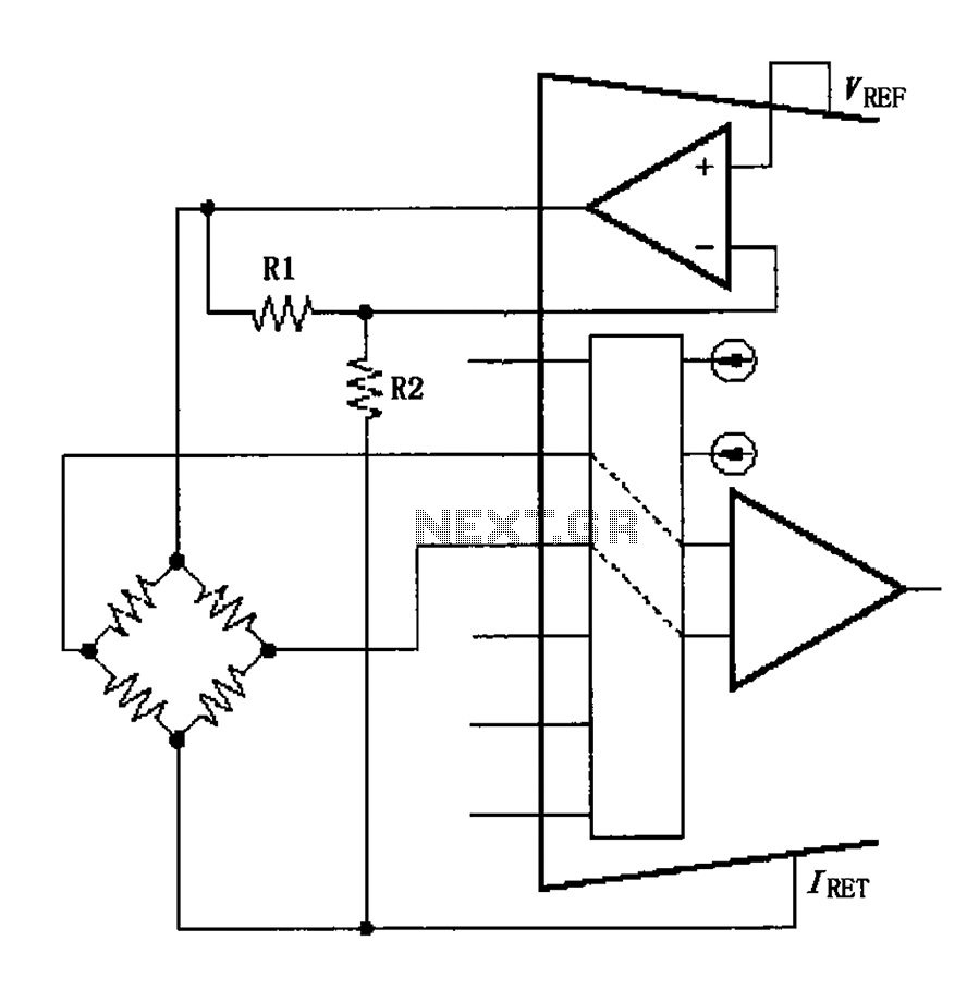
The circuit voltage source VREF excites the sensor bridge. The excitation voltage VEX is defined as VREF (1 + R1/R2), where the bridge is connected at both ends. The sensor bridge circuit is designed to convert a physical quantity, such...