
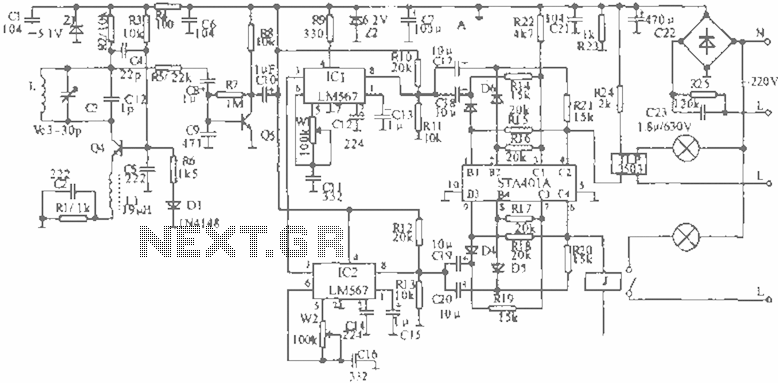
Light control principle circuit rooster crows

The described circuit operates as a light-sensitive activation system that controls sound output based on ambient light conditions. The core component, a photosensitive resistor (RG), is pivotal in determining the circuit’s response to light levels. During nighttime, RG maintains a high resistance, which keeps the output of the LSE pin low. This low output signals transistor VT1 to conduct, thereby energizing relay J. The relay's normally closed contacts open, effectively disconnecting power from the chicken sounds analog circuit IC KD5609, silencing the output.
As dawn approaches and light levels increase, the resistance of RG decreases significantly, reaching approximately 50K. This change triggers a transition in the LSE pin output to high, which turns off transistor VT1. The deactivation of VT1 allows relay J to return to its default state, closing its contacts. This closure restores power to the IC KD5609, activating the chicken sounds circuit. The result is an engaging auditory experience, with realistic chicken sounds produced through the speaker BL, thereby simulating a natural morning environment.
The circuit can be utilized in various applications, such as in educational projects, automated farm settings, or as a novelty alarm clock feature. Proper component selection is essential for ensuring that the photosensitive resistor and transistor can handle the expected ranges of light and current. Additionally, the relay must be rated to manage the load of the connected sound circuit. Overall, this light-activated circuit exemplifies a practical implementation of basic electronic principles to create an interactive and responsive system. Circuit principle is shown in FIG apparatus. When the night light irradiation on the photosensitive resistor RG, RG of great resistance, (much larger than 50K), so the LSE O, f eet equivalent open, LSEs pin output low, transistor VT1 conduction, excitation relay J pull its normally closed contacts j oFF, chicken sounds analog circuit IC KD5609 does not work without power. Once dawn, light irradiated on the RG, RG internal resistance becomes smaller ( 50K), this time the LSE pin output high, the transistor VT1 end, the relay J release, closes its contact j, analog sounds of chickens circuit energized work, accompanied by realistic sounds of chickens from the indicator in the speaker BL.
Related Circuits
When the infrared receiver tube PH302 receives a signal from the remote control, the CX20106A selected frequency amplifier outputs a low-frequency signal. The low-level signal charges capacitor C through diodes D and R, causing the negative side potential of...
A new user has joined the forum and is seeking assistance with circuit design. They express a desire for guidance and acknowledge their inexperience in the subject. In circuit design, it is crucial to understand the fundamental components and their...
In certain industries, a computer-controlled 4-20 mA current loop is utilized to manage various equipment. This current loop is employed to transmit a signal over a distance. The 4-20 mA current loop is a standard method for transmitting analog signals...
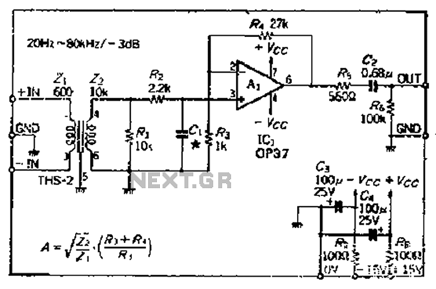
The common mode signal rejection ratio is influenced by the input transformer, which should either be a commercially available or a well-balanced homemade transformer. It is important to note that as frequency increases, the balance may decrease. The transmission...
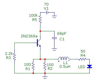
This article presents basic circuits for pulsing infrared LEDs and low-power visible semiconductor lasers utilizing inexpensive and readily available components. Numerous interesting and practical applications are referenced, alongside several online resources. The focus of the article is on the...
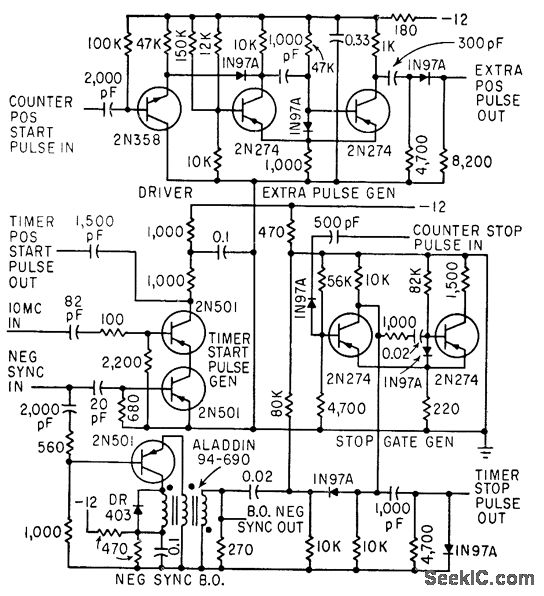
The timer start-pulse generator is a fast series-transistor coincidence circuit. The slope-gate generator is a one-shot multivibrator that prevents the 1N97A diode from passing the blocking oscillator's negative sync pulse until the multivibrator fires. This circuit is utilized to...