
Brushless DC motor control circuit
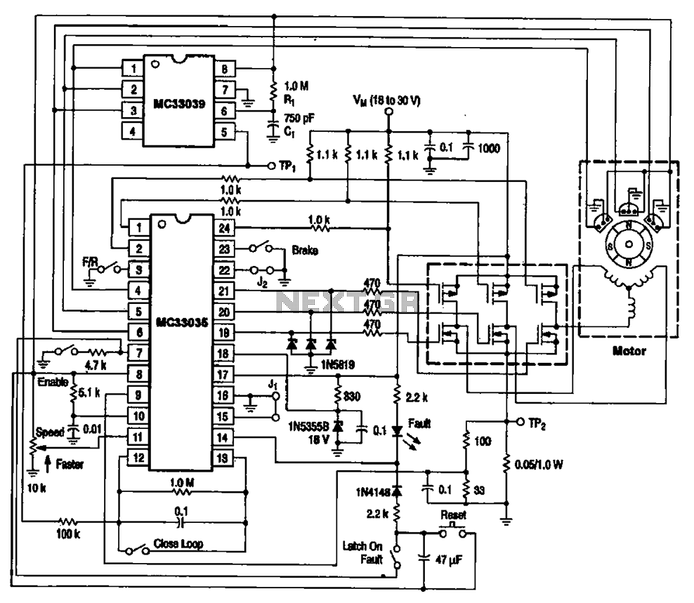
The brushless DC motor control circuit is designed to efficiently manage the operation of brushless motors, which are known for their high efficiency and reliability. The MC33035 serves as the primary control unit, generating pulse-width modulation (PWM) signals that regulate the speed and torque of the motor. The MC33039 complements this functionality by providing additional control features, such as over-current protection and thermal shutdown.
In the circuit, the six field effect transistors (FETs) are configured in a three-phase bridge arrangement, allowing for precise control of the current flowing through each motor winding. The sequential activation of the FETs is crucial for generating a rotating magnetic field. This field interacts with permanent magnets on the rotor, resulting in continuous rotation.
The design of this circuit is particularly beneficial for applications requiring precise speed control and high torque at low speeds. Furthermore, the integration of the MC33035 and MC33039 offers a compact solution that minimizes component count while maximizing performance. The use of FETs ensures rapid switching times and high efficiency, contributing to the overall effectiveness of the motor control system.
In summary, the brushless DC motor control circuit utilizing the MC33035 and MC33039 chips provides a sophisticated solution for controlling brushless motors, ensuring efficient operation and precise control through a well-designed arrangement of power electronics. Brushless DC motor control circuit MC33035 and MC33039 uses a combination of the control circuit is shown in Figure A typical brushless DC motor control circuit, which is mainl y driven by the motor control chip MC33035 and MC33039 brushless motor adapter and field effect transistors and other parts of the drive circuit. At work. MC33035 output channel 6 I-WM signals to drive the motor driving circuit 6 by a field effect transistor.
It is seen from six field effect transistor bridge circuit. Outputs are connected to the three-phase motor winding. Three-phase current in the windings sequentially changed according to the law, to form a rotating magnetic field, the rotor of the drive motor continuously rotates.
Related Circuits
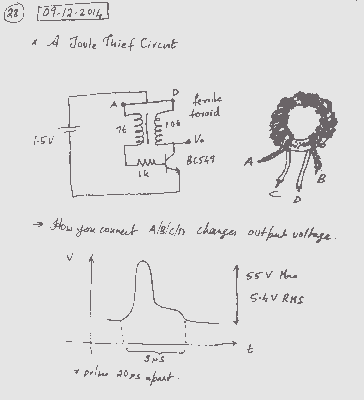
A simple voltage boost circuit known as the Joule Thief has been identified for construction. The Joule Thief is a minimalist boost converter designed to extract energy from low-voltage sources, such as depleted batteries, and increase the voltage to a...

The I2C PIC Interfacing Tutorial circuit is relatively straightforward; however, it requires careful verification to ensure that all connections are correct before initial operation. The primary components utilized in this circuit include the PIC18F452 microcontroller, the 24LC02B EEPROM, and...
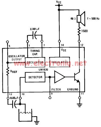
The LM1830 low-level detector can utilize an audio indication (speaker) or a visual indicator (LED - light-emitting diode) that activates when the level is too low. This low-level detector circuit generates a 500 Hz audio signal when the level...
This page is provided to the domain owner free by Sedo's Domain Parking. Disclaimer: The domain owner and Sedo maintain no relationship with third-party advertisers. References to any specific service or trademark are not controlled by Sedo or the...
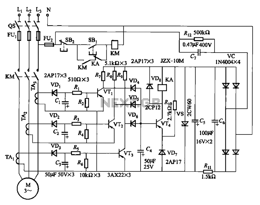
The current detection signal is obtained from three current transformers after rectification and filtering, resulting in three DC voltage outputs. These voltages are applied to transistors VT1, VT2, and VTa between the base and emitter. The signal is amplified...
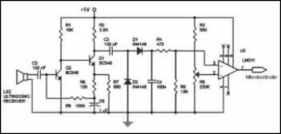
Ultrasonic receivers detect an ultrasonic signal emitted by an ultrasonic transmitter at a specific frequency. The received signal is filtered using a band-pass filter circuit that allows only the predetermined frequency range to pass. The output signal is then...