
I2C PIC Interfacing Tutorial Circuit

The I2C PIC interfacing circuit is designed to facilitate communication between the PIC18F452 microcontroller and the 24LC02B EEPROM, while also displaying data on a 16x2 LCD. The circuit operates on a regulated 5V power supply provided by the LM7805 voltage regulator, which ensures stable operation even with varying input voltages. The use of a heatsink is essential for the LM7805, as it dissipates heat generated during voltage regulation, thereby maintaining the reliability of the circuit.
The I2C protocol is a widely adopted communication standard in embedded systems, allowing multiple devices to communicate over a two-wire interface. The SDA line transmits data, while the SCL line provides the clock signal necessary for synchronization between the master (PIC18F452) and slave (24LC02B) devices. The inclusion of pull-up resistors is critical in open-drain configurations to ensure that the lines can be pulled high when not actively driven low by the devices, thus enabling proper signal levels.
The choice of using a 4-bit data interface for the LCD simplifies wiring and reduces clutter on the breadboard, which is particularly beneficial for prototyping. In this configuration, the microcontroller sends data in two sequential 4-bit transmissions, effectively allowing for the same data throughput as an 8-bit transmission but with fewer physical connections. This design choice balances practicality and functionality, making it suitable for educational demonstrations and small-scale projects.
In conclusion, this I2C PIC interfacing circuit exemplifies a fundamental approach to integrating microcontrollers with peripheral devices, showcasing essential concepts in embedded system design, such as power regulation, communication protocols, and efficient data handling. Proper attention to detail in the circuit assembly and software implementation is crucial for achieving reliable operation and successful data exchange.The I2C PIC Interfacing Tutorial circuit is not terribly difficult however it will take some double checking to make sure you have everything hooked up properly before working the first time. The main devices used in the circuit are the 18F452, 24LC02B and 16x2 LCD. The power circuit uses a LM7805 +5 voltage regualtor. Stick in an voltage over +6. 5v and it gets regulated down to +5v with excess power exhausted through the heatsink. This is a standard power circuit that I`ve used in most all my tutorials, nothing extra-ordinary. here The I2C Interface From PIC to the EEPROM (24LC02B) is 2 wires, SDA and SCL. *Special Note*: The two resistors 1k and 10k connected to +5v are critical if you want your I2C interface to work properly. You must have at least a 10k resistor connected to +5v or nothing will work. This is due to the fact that SCL and SDA are `open drain`, which means I2C devices can drive signals low to +0v but not high to +5v.
The LCD used in this tutorial will only use 4 data-bits, mostly because I was too lazy to use 8 wires and things would start to look too cluttered on a breadboard with that many wires. The 4-bit interface just requires you to send data in two 4-bit sequences instead of in 1 8-bit sequence.
Look at the software to see this difference. 🔗 External reference
Related Circuits
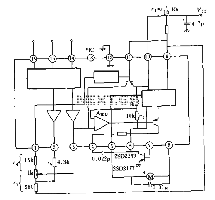
The AN6657 is a 16-pin dual in-line plastic package, while the AN6657S features a 16-pin dual flat plastic package. The speed control function operates with an internal H-bridge driver chip circuit, utilizing pins 5 and 8 for H-bridge driver...

A precision circuit utilizing the LM567 timer, specifically the MPI826, where the LM567 functions as a dual-band oscillator. The MP1826 serves as a divider in the circuit, allowing the output signal from the LM567 to achieve extended timing. The...
The loop can be any type of hookup wire, with a maximum resistance of about 90K. Using very thin wire (40AWG, for example) will create a highly sensitive trip wire, but will reduce the distance it can be strung...
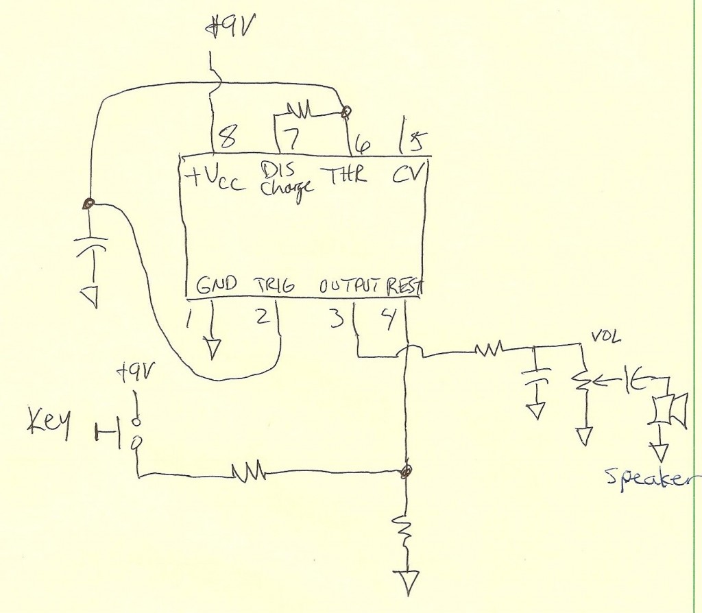
A code practice oscillator was built some time ago, and there is a vague recollection of the project. It featured a straight key that plugged directly into the key jack. Upon opening the device, a circuit board populated with...
For the simplest functions, such as a flashing indicator and/or beeper, a printed circuit board is not necessary. Components can be directly soldered onto the legs of the PIC microcontroller, using heat-shrinkable sleeves for insulation. Caution is advised to...

This circuit is a simple two-transistor (2N2222) mini FM transmitter. No authorization is required for this transmitter according to FCC regulations regarding wireless microphones. When powered by a 9-volt battery and equipped with an antenna no longer than 12...