
A Joule Thief Circuit

The Joule Thief is a minimalist boost converter designed to extract energy from low-voltage sources, such as depleted batteries, and increase the voltage to a usable level. This circuit is particularly useful for powering low-current devices from single-cell batteries, enabling the utilization of nearly all the energy stored within the battery.
The core components of a Joule Thief circuit typically include a transistor, a resistor, a toroidal ferrite core, and a small inductor or winding. The circuit operates on the principle of oscillation, where the transistor switches on and off rapidly, creating a magnetic field in the inductor. When the transistor is turned off, the collapsing magnetic field induces a voltage spike, which can be significantly higher than the original supply voltage.
To construct the Joule Thief, the following steps outline the necessary components and connections:
1. **Transistor**: A small-signal NPN transistor, such as the 2N3904 or BC547, is used as the main switching element. The transistor's collector is connected to one end of the inductor.
2. **Inductor**: A toroidal ferrite core is wound with a few turns of insulated copper wire to form the inductor. Typically, around 10 turns can be sufficient. One end of the inductor connects to the collector of the transistor, while the other end connects to the positive terminal of the power source.
3. **Resistor**: A resistor (commonly between 1kΩ and 10kΩ) is connected from the base of the transistor to the positive terminal of the power source. This resistor helps to bias the transistor, allowing it to switch on.
4. **Feedback Loop**: A feedback winding is created by adding a few turns of wire around the same core, connecting this feedback winding to the base of the transistor. This feedback is crucial for sustaining oscillation.
5. **Power Source**: The circuit can be powered by a single AA or AAA battery. The negative terminal of the battery connects to the emitter of the transistor.
6. **Output Load**: The output voltage can be taken from the collector of the transistor. The circuit can drive low-power LEDs or other devices that operate at higher voltages than the source.
The Joule Thief circuit is efficient and can extend the life of batteries by utilizing energy that would otherwise be wasted. This simple design demonstrates the principles of energy conversion and oscillation in electronics, making it an excellent project for both educational purposes and practical applications.I was looking for a simple voltage boost circuit when I found that Joule Thief. Now lets look at building the circuit. 🔗 External reference
Related Circuits

The circuit diagram and detailed explanation of a simple aircraft radio circuit are provided below. The simple aircraft radio circuit typically consists of several key components that work together to facilitate communication between the aircraft and ground stations or other...
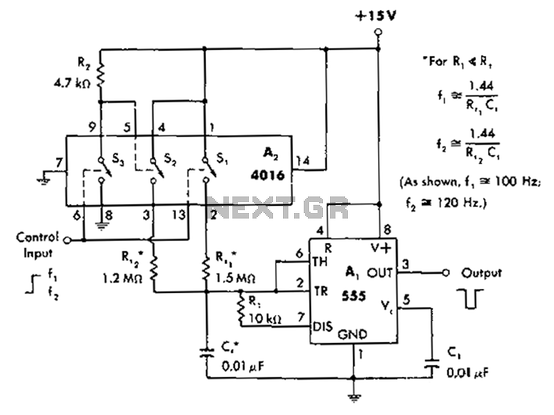
A circuit diagram controls the timing based on the input line state. When the input line is high, the 4016 CMOS analog switches select the timing of a 1.5 megohm resistor (Rt1) to produce negative output pulses at a...
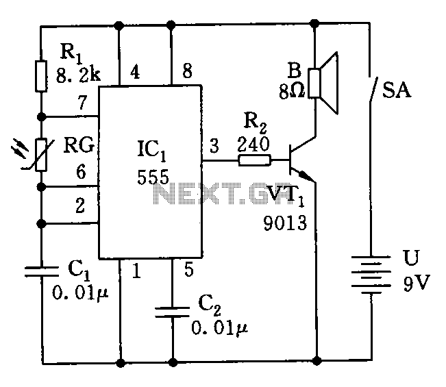
The electronic circuit simulates bird sounds under varying lighting conditions, particularly influenced by neon light irradiation, resulting in fluctuating and changing tones. The sound produced is continuously variable. The schematic of this circuit is provided. The described electronic circuit utilizes...
The inverter circuit diagram utilizing the NE555 timer is illustrated, designed to convert a +12V DC battery voltage into a 220V AC output voltage. In this circuit, the NE555 functions as an oscillator, with the oscillation frequency determined by...
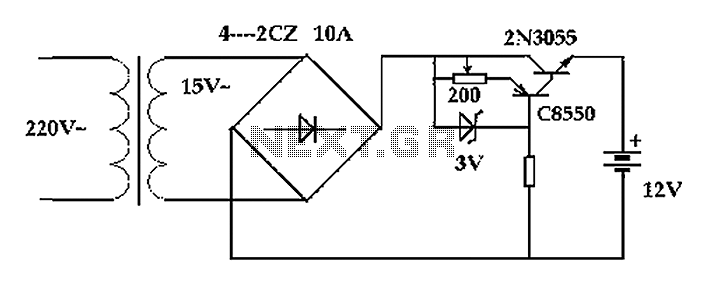
The circuit operates after a transformer, utilizing a bridge rectifier and conditioning for battery charging. The charging current transformer can be easily adjusted to provide approximately 12V at 100Ah battery charging. The required charging current is 10A, and a...
This circuit serves as a dependable alternative to thermally-activated switches designed for flashing Christmas tree lamps. The arrangement consisting of Q1, Q2, and associated resistors activates the silicon-controlled rectifier (SCR). The timing function is determined by resistors R1, R2,...