
Current three-phase motor phase protection circuit diagram
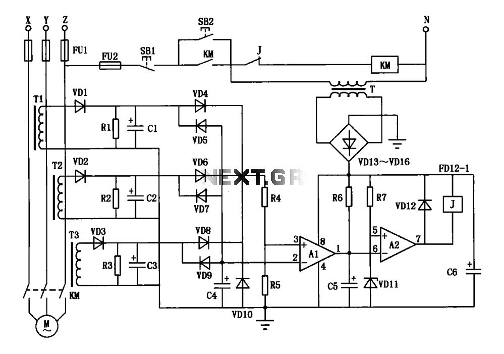
The current three-phase motor phase protection circuit is structured to ensure reliable operation of three-phase motors by monitoring the current flow through each phase. The use of small current transformers (T1, T2, T3) allows for accurate detection of the motor's current without direct electrical connections, thereby enhancing safety and reducing wear on components.
The rectification process, facilitated by diodes VD1, VD2, and VD3, converts the AC signals from the transformers into DC signals, which are then filtered by capacitors C1, C2, and C3 to remove any ripple, ensuring a stable voltage for the subsequent processing stages. The OR gate circuit, composed of resistors R4 and R5, is critical for voltage level adjustment, allowing the comparator A1 to receive a suitable input for accurate monitoring.
Comparator A1 plays a pivotal role in determining the operational status of the motor. It compares the voltage from the OR gate circuit and the input from the diodes VD5, VD7, and VD9, which are configured to detect current presence or absence. This dual comparison ensures that any phase loss or imbalance triggers appropriate protective measures, preventing potential motor damage.
Transformers T1 to T3 are designed using toroidal ferrite cores, known for their efficiency in reducing electromagnetic interference. The winding specifications (150 to 250 turns) are tailored to the motor's power requirements, allowing for flexibility in application. The primary winding is ingeniously created by routing the power cord through the toroidal core, optimizing space and minimizing installation complexity.
Capacitors C1 to C3, with their specified ratings, are integral to the circuit's performance, providing necessary filtering and stabilization. Capacitor C5, which serves as an interference absorption component, can be fine-tuned to adjust the circuit's sensitivity, allowing for customization based on the specific operational environment.
The resistors in the circuit are carefully selected for their values and power ratings, ensuring that they can handle the expected current without overheating. The inclusion of a Zener diode (VD11) for voltage regulation adds an additional layer of protection, maintaining stable operation across varying input conditions.
Overall, this circuit design exemplifies an effective approach to three-phase motor protection, combining reliable detection, filtering, and voltage regulation to enhance motor longevity and performance.Current three-phase motor phase protection circuit, as shown in FIG. 3 homemade small current transformers Tl, T2 and T3 on the motor is running three-phase current detection s ignals are collected by the VDl, VD2 and VD3 rectifier, Cl, C2 and C3 filter by VD4, VD6 and VD8 oR gate circuit is composed of R4, R5 partial pressure of the supplied voltage comparator Al-inverting terminal; the gate as a three-phase current output circuit to identify the presence or absence VD5, VD7, VD9 composed of input voltage comparator Al counter phase terminal.Transformer Tl ~ T3 making available on the market Tesco toroidal ferrite core with µ0.25mm high-strength wire, winding 150 to 250 turns. The number of turns is determined by the power of the motor, motor power small can around more. Through the power cord from the ring, as the primary winding. Capacitor C1 ~ C3 electrolytic capacitor 10 F/25V of; C4 use 0.1 F/63V ceramic capacitors; C6 electrolytic capacitor 470 F/25V is; C5 is interference absorption capacitor, to increase the capacitance value C5 when the action is too sensitive, Conversely reduce the value of C5, which is in the range of 4.7 ~ 33 F/25V.
Resistance Rl R2 l.2k, R4 390k, R5 680k, R6 15k, R7 2k, nominal power are RJ resistance 1/8W of. Zener diode VD11, which the regulator is about 8V. Other diodes with 1N4004.
Related Circuits
This is a non-contact power regulator circuit designed for a light load. By adjusting a 150kΩ potentiometer, phase shift can be achieved, and a trigger voltage is applied to the gate of a bidirectional thyristor through a bidirectional trigger...
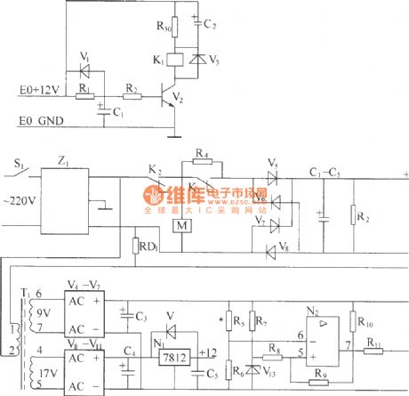
220V (50Hz) alternating voltage passes through the Z1 circuit filter, which filters the signal before sending it to the connection point of the AC overvoltage and undervoltage protection relay K2. During normal operation, the K2 connection point should be...

This is a design circuit diagram of a moderate power FM transmitter circuit. The circuit operates using two transistors. It consists of a complete circuit diagram. The operation of this circuit is explained as follows: the voice signals picked...
The two unspecified polarized capacitors (one directly above the transformer and one directly to the right of the transformer) are actually each a pair of 470 µF capacitors in parallel (for a total of four 470 µF capacitors). These...
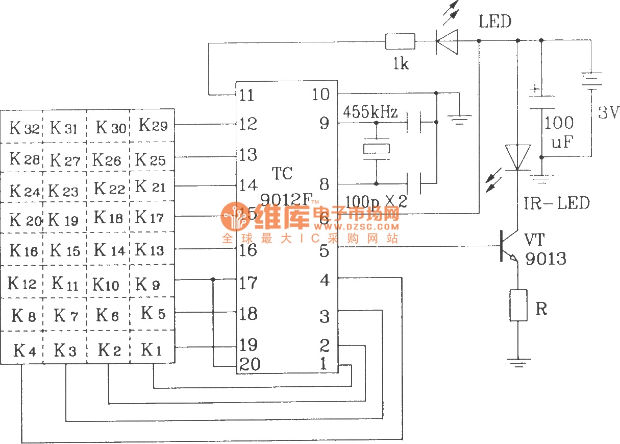
The TC9012 is a specialized off-screen remote control code transmitter. It incorporates an oscillator, divider timing generator, system code latch, data storage, key scan input, key scan output, and carrier control and output units. The internal 8-bit system code...

This circuit is used to select modes of operation. The accelerometer is utilized to generally move the snake arm, while the Hall effect sensors are designed to enable various functions. The circuit described incorporates an accelerometer and Hall effect sensors...