
Thyristor circuit with 100W 700W and 1000W output power

The non-contact power regulator circuit operates by utilizing a bidirectional thyristor, which allows for the control of AC loads without direct electrical contact. The circuit is designed to modulate the power delivered to a load, in this case, a light load, by adjusting the phase angle of the AC waveform. The phase shift is achieved through the use of a 150kΩ potentiometer, which alters the timing of the trigger signal sent to the thyristor gate.
The circuit is powered by a standard AC supply voltage of 220 V, with a tolerance of ±10%, making it versatile for various applications. The output voltage can be adjusted between 10 V and 230 V, providing flexibility in controlling the brightness or power of the connected load. The power ratings of 100 W and 700 W indicate that the circuit can handle a range of load requirements, making it suitable for different lighting applications.
In operation, the bidirectional trigger circuit ensures that the thyristor is turned on at the desired phase angle, which is determined by the setting of the potentiometer. This allows for smooth control over the power delivered to the load, enhancing energy efficiency and extending the lifespan of the connected devices. The design of the circuit is focused on simplicity and effectiveness, making it an ideal solution for applications requiring non-contact power regulation.This is a non-contact power regulator circuit, the load is light La. To change 150k? potentiometer can achieve phase shift, and adding trigger voltage to bidirectional thyristor gate through bidirectional trigger, to control the conduction. Main technical data: network voltage: 220±10%V; the adjustable range of output voltage: 10~230V; power: 100W, 700W..
🔗 External reference
Related Circuits
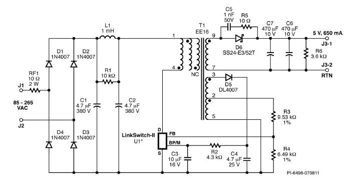
A simple 3.25W constant voltage/constant current (CV/CC) charger can be designed using the LinKSwitch family IC manufactured by Power Integrations. This electronic circuit project is intended to provide a 5-volt output with a maximum current of 650mA. The 3.25W...
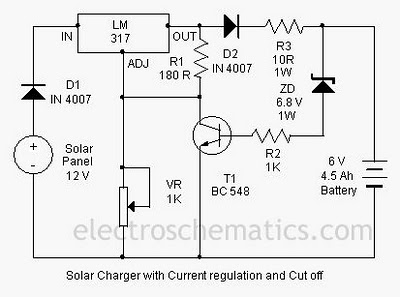
A solar charger circuit is designed to charge lead-acid batteries or nickel-cadmium (Ni-Cd) batteries using solar power. This circuit captures solar energy to charge a 6-volt, 4.5 Ah battery for various applications. It features voltage and current regulation along...
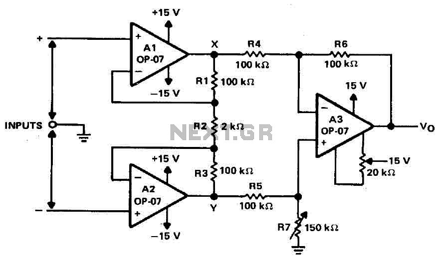
Operational amplifiers A1 and A2 are connected in a non-inverting configuration to form amplifier A3. The operational amplifier A3 can be classified as a subtractor circuit that converts the differential signal between the floating points X and Y into...
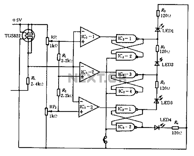
Ceramic gas sensors can be utilized to analyze the content of alcohol vapor. With the appropriate sensor circuit, it is possible to detect blood alcohol content. The operating principle is straightforward: if blood alcohol content is present in a...

The LED meter circuit is more compact and simpler than its analog equivalent, making it a common choice in audio equipment. This circuit utilizes the LM3915 integrated circuit (IC) and operates in a logarithmic mode. It comprises a single...
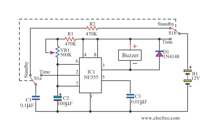
This is a simple and compact timer circuit (Egg Timer) using the IC 555. It features an alarm activated by a buzzer. This mini timer circuit is quite interesting and is referred to as the Egg Timer. The circuit utilizes...