
Push Button Motor Control Circuits
The motor control circuits described are designed to facilitate the operation of electric motors through the use of push buttons. These circuits are essential in various applications, including manufacturing, automation, and machinery control. The push buttons serve as the primary user interface, allowing operators to start, stop, or control the speed of the motor as required.
In a typical setup, the circuit may include components such as relays, contactors, fuses, and overload protection devices. The relays act as switches that control the power supply to the motor, while the contactors provide the necessary current capacity to handle the motor load. The inclusion of relay holding contacts ensures that once a push button is activated, the circuit remains energized even after the button is released, thereby maintaining motor operation until a stop command is issued.
Interlock contacts are also critical in these circuits, as they provide safety by preventing simultaneous operation of motors that could lead to mechanical conflicts or hazards. For instance, in a system where multiple motors are controlled, interlock contacts ensure that one motor cannot be started if another is already running, thus protecting both the equipment and operators.
The specific wiring configuration for the motors is not included, as it varies based on the motor type, whether it's an AC or DC motor, and its specific operational requirements. The number of contacts needed on the motor side will depend on the motor's specifications and the complexity of the control system being implemented.
In summary, the circuits utilizing push buttons for motor control are foundational elements in industrial and commercial applications, ensuring efficient and safe operation of electric motors while allowing for user-friendly interaction through simple push-button controls.The circuits on this page are for motor controls using Push buttons and would typically be found in commercial and industrial installations. The circuits do not show the wiring of the motors themselves as this depends on the particular motor type.
The type of motor also governs the number of contacts needed for the motor side of these circuits. The "Relay Holding Contacts" and the "Interlock Contacts" shown in these circuit would normally be built into the motor control relays. 🔗 External reference
Related Circuits
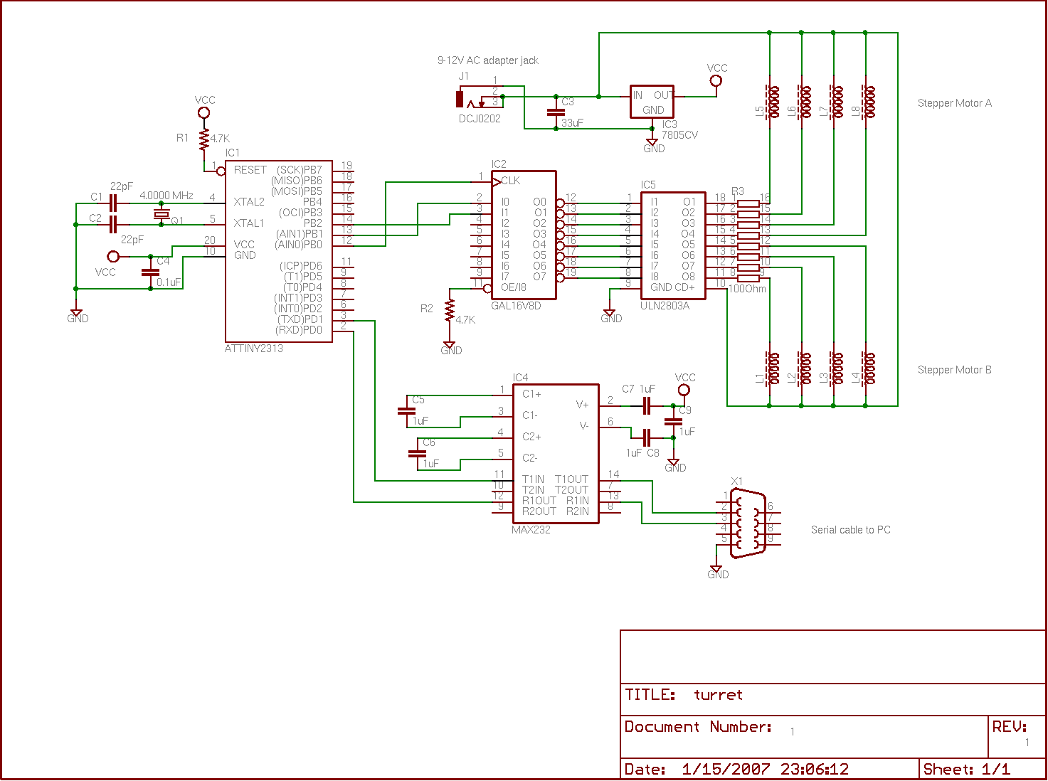
A tiny speedometer/trip computer was constructed using an Atmel ATTiny2313 microcontroller and an HD44780-compatible character LCD display, along with a reed switch and magnets. This device measured the speed of a soapbox derby cart by attaching a permanent magnet...
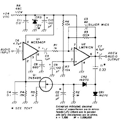
An audio signal applied to VI is passed through the operational amplifier 741, U2. After being amplified, the output signal V2 is sampled and applied to a negative voltage doubler/rectifier circuit composed of diodes CR1 and CR2, along with...
When a key is pressed, the remote control transmits a preamble followed by 32 bits of information encoded using specific pulse timings. The pulse examples can be observed in logic analyzer screen captures, although some glitches are present due...
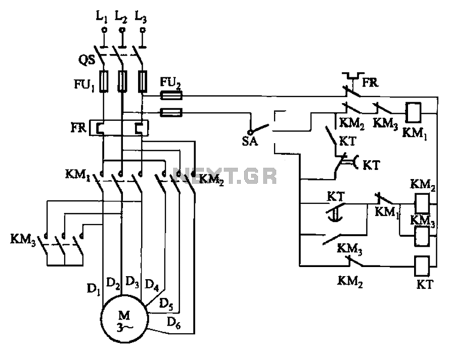
The circuit depicted in Figure 3-98 demonstrates how motor starting and low-speed operation are managed using switch SA. By adjusting the time relay KT, the motor's operation can transition from low speed to high-speed operation within a specified time...
The controller is a prototype and works well in my plane with 7 cells and a Graupner-Speed 600. The described controller is a prototype designed for use in a model aircraft, specifically optimized to operate with a battery pack consisting...
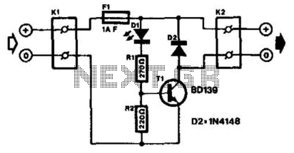
The LED with an integrated flasher is connected in series with the base-emitter junction of transistor T1. Consequently, the load connected to K2 is switched on and off in sync with the flash rate. This load can be a...