
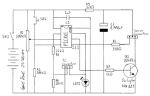
Flashing Led Controller

The described circuit utilizes an LED with an integrated flasher, which serves as a visual indicator while simultaneously controlling a load through a transistor switch. The LED is connected in series with the base-emitter junction of a bipolar junction transistor (BJT), specifically the BD139. This configuration allows the LED to modulate the transistor's operation, effectively switching the connected load on and off at a defined flash rate.
The load, which can either be a relay or a lamp, is connected to terminal K2. The operation of the load is directly influenced by the switching action of the transistor, which is driven by the LED's flashing. It is crucial to ensure that the collector current of the BD139 does not exceed its maximum rating of 750 mA. Should the application require a higher current capacity, a power Darlington transistor can be used as an alternative. Darlington transistors are known for their high current gain, allowing them to switch larger loads while maintaining a compact design.
Under no-load conditions, the circuit draws a current of 20 mA, which is relatively low, making it suitable for battery-operated devices or applications where power efficiency is essential. Proper consideration of the load's power requirements and the transistor's specifications will ensure reliable operation and longevity of the circuit. The LED with integrated flasher is connected in series with the base-emitter junction of transistor Tl. Thus, the l oad connected to K2 is switched on and off in rhythm with the flash rate. This load can be a relay or a lamp. The maximum collector current of the transistor (of the BD139 = 750 mA) must not be exceeded. If that is not sufficient, a power Darlington can be used, which will give some amperes. The current drawn by the circuit under no-load conditions amounts to 20 mA.
Related Circuits
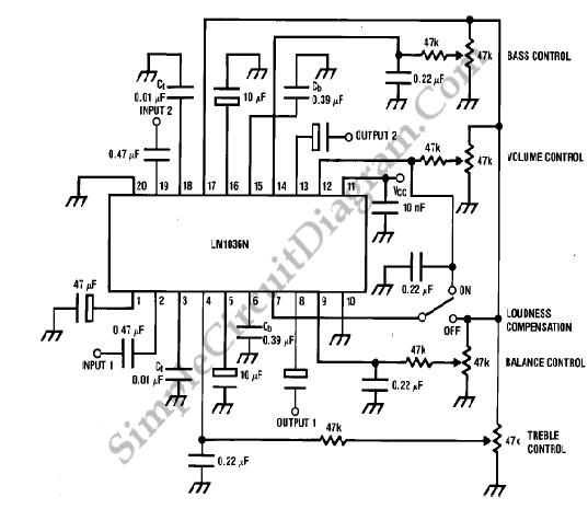
The LM1036 is a DC-controlled circuit designed for tone adjustment (bass/treble), volume control, and balance. It is suitable for use in car radios, televisions, and audio systems. The circuit also incorporates loudness compensation. The LM1036 integrates several functionalities essential for...
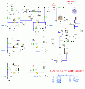
This circuit consists of a 6 Zone Alarm system with an LED display. The alarm system features 6 independent zones and includes a 7-segment LED display, along with one timed entry/exit zone. The 6 Zone Alarm system is designed to...

This circuit is designed as a warning flasher to alert road users to dangerous situations in low-light conditions. It can also function as a bicycle light, adhering to traffic regulations. White LEDs are recommended for use as a front...

This is a servo system controller circuit designed for remote control of a servo motor. The circuit utilizes a 555 timer and requires only six additional components. The servo system controller circuit operates by generating a pulse-width modulation (PWM) signal,...
This project involves creating a programmable camera controller using basic hand tools and a digital camera. By utilizing components that are commonly found at home, the overall costs can be minimized. A servomotor can be repurposed from a radio-controlled...
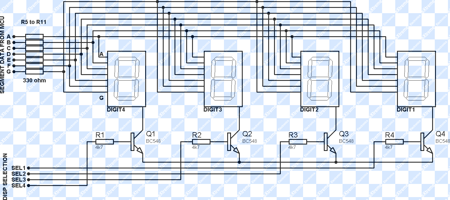
The project involves displaying the current room temperature using an LM35 temperature sensor. This schematic differs from a previous schematic that utilized a multiplexed seven-segment display. In the earlier schematic, the display select I/O pins were RA0, RA1, RA2,...