
Simple AC Motor Speed Controller
The described circuit serves as a speed control mechanism for AC motors, utilizing a combination of rectification and phase control techniques. The bridge rectifier is essential for converting the alternating current (AC) from a 120V source into direct current (DC), which is necessary for controlling the SCR (Silicon Controlled Rectifier).
The 10K ohm potentiometer allows for variable resistance, enabling the user to adjust the voltage and current flowing through the circuit. This adjustment directly influences the gate signal fed to the SCR, thus controlling the phase angle of the AC waveform applied to the motor. The inclusion of two 100 ohm resistors in the circuit may serve as current limiters or voltage dividers, ensuring that the gate of the SCR receives an appropriate signal without exceeding its maximum ratings.
The 50µF capacitor plays a critical role in filtering and smoothing the output from the rectifier, stabilizing the voltage supplied to the SCR. This capacitor also aids in reducing voltage spikes that could potentially damage sensitive components, particularly the SCR.
Diode D1 is integrated into the circuit to protect against reverse voltage spikes, which can occur when the motor is switched off or experiences sudden changes in load. This diode should be rated for at least 2 amps and possess a peak inverse voltage (PIV) rating of 600 volts to ensure reliable operation under varying conditions.
The bridge rectifier and SCR must be rated for 25 amps and 600 volts PIV, which provides a safe margin for operation, especially considering the circuit's capability to handle loads of up to 10 amps. Proper thermal management is crucial; therefore, the SCR should be equipped with an adequate heat sink to dissipate excess heat generated during operation, preventing thermal overload and ensuring longevity.
Overall, this circuit effectively combines various electronic components to achieve precise control over an AC motor's speed, making it suitable for applications such as electric drills and other variable-speed tools.This circuit will allow you to control the speed of an AC motor, for example an electric drill. The way that this circuit works is as follows. The bridge rectifier produces dc voltage from the 120vac line. A portion on this current passes through the 10K ohm pot. The circuit comprised of the 10k pot, the two 100 ohm resistors and the 50uf capacitors delivers gate drive of the SCR. The diode D1 protects the circuit from reverse voltage spikes. The ratings of the bridge rectifier and the SCR should be 25 amps and PIV 600 volts. The diode D1 should be rated for 2 amps with PIV of 600 volts. The circuit can handle a load up to 10 amps. The SCR should be very well heat sinked. 🔗 External reference
Related Circuits
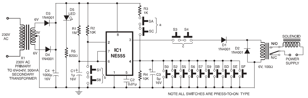
In these circuits, a set of switches (conforming to code) are pressed sequentially within a specified time to unlock the mechanism. In some configurations, custom-built integrated circuits (ICs) are utilized, and positive and negative logic pulses are input in...
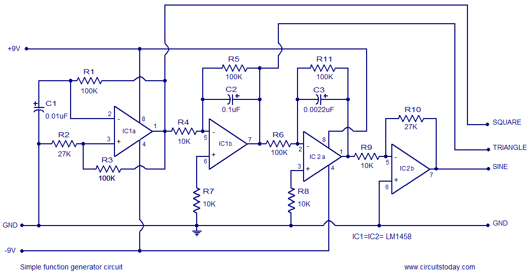
A simple function generator circuit utilizing the LM1458 is presented here. The LM1458 is a dual general-purpose operational amplifier. The two op-amps within the LM1458 share a common bias network and power supply line, yet operate independently. The function generator...
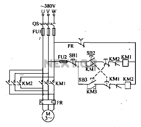
The forward and reverse dual interlock control circuit is based on the control circuit depicted in Figure 4-4, with an enhancement that incorporates a composite mechanical button interlock. The advantage of this circuit is that it allows the motor...
The above pictured schematic diagram is just a standard constant current model with a added current limiter, consisting of Q1, R1, and R4. The moment too much current is flowing biases Q1 and drops the output voltage. The output...
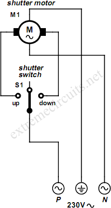
An electrically operated rolling shutter typically features a standard control panel equipped with a three-position switch: up, down, and stop. To automate the opening and closing of the shutter using a time-controlled switch, additional wiring connections are necessary. The...
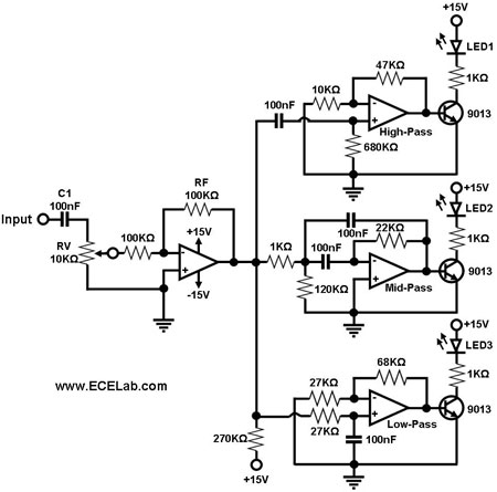
Figure 1 illustrates a simple circuit designed for converting an audio signal (such as one from the output terminals of a CD player). The circuit primarily consists of a buffer/amplifier stage and three filtering circuits: a high-pass filter, a...