
Double interlocking three-phase asynchronous motor control circuit

The forward and reverse dual interlock control circuit is designed to enhance the operational safety and reliability of motor control systems. The circuit employs a combination of mechanical and electrical interlocks to prevent simultaneous activation of forward and reverse operations, which could otherwise lead to equipment damage or hazardous conditions.
In this circuit, two start buttons, SB3 and SB4, are utilized for forward and reverse motor operations, respectively. The mechanical interlock ensures that pressing one button will physically prevent the other from being engaged, thereby enforcing a clear operational protocol. The electrical interlock further reinforces this by using relay contacts that disengage the opposite start button when one is activated.
The circuit typically includes a power source connected to the motor through a relay system. When the user presses the forward start button (SB3), the relay engages, allowing current to flow to the motor in the forward direction. Simultaneously, the mechanical interlock prevents the reverse button (SB4) from being pressed. If the user wishes to change the direction of the motor, they can simply press the reverse button (SB4) without needing to first stop the motor with SB1. The electrical interlock ensures that the motor is safely stopped before reversing direction, thus preventing any potential damage.
In addition to the interlock features, the circuit can be designed to include indicator lights that signal the current operational status of the motor (forward, reverse, or stopped). This provides visual feedback to the operator, enhancing safety and operational awareness.
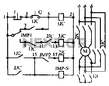
Overall, the forward and reverse dual interlock control circuit is a sophisticated solution for controlling motor operations, emphasizing safety, reliability, and user convenience in various industrial and commercial applications.Shown in forward and reverse dual interlock control circuit, on the basis of the control circuit in Figure 4-4 on the increase in the composite mechanical buttons mutual lock link. The advantage of this circuit is: If you want to run the motor forward reverse, do not press the stop button SB1, as long as the direct anti-press to turn the start button SB3; of course, from forward to reverse operation, as well. This circuit has a dual electrical and mechanical interlock, not only to improve the reliability of control, and can achieve a reverse forward a stop a stop control, but also to achieve a forward reverse a stop control.
Related Circuits
This circuit is designed to detect the approximate percentage of salt in a liquid. After careful calibration, it can provide a quick, rough indication of salt content in liquid foods for dietary purposes. The operational amplifier IC1A is configured...
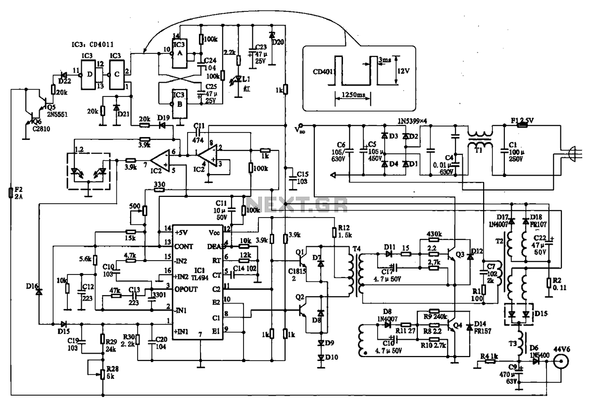
The TN-1 Intelligent Negative Pulse Charging Circuit is a sophisticated device designed for efficient battery charging. It operates as a half-bridge charger, which is a common configuration in such circuits. The negative pulse charging mechanism is facilitated by a...
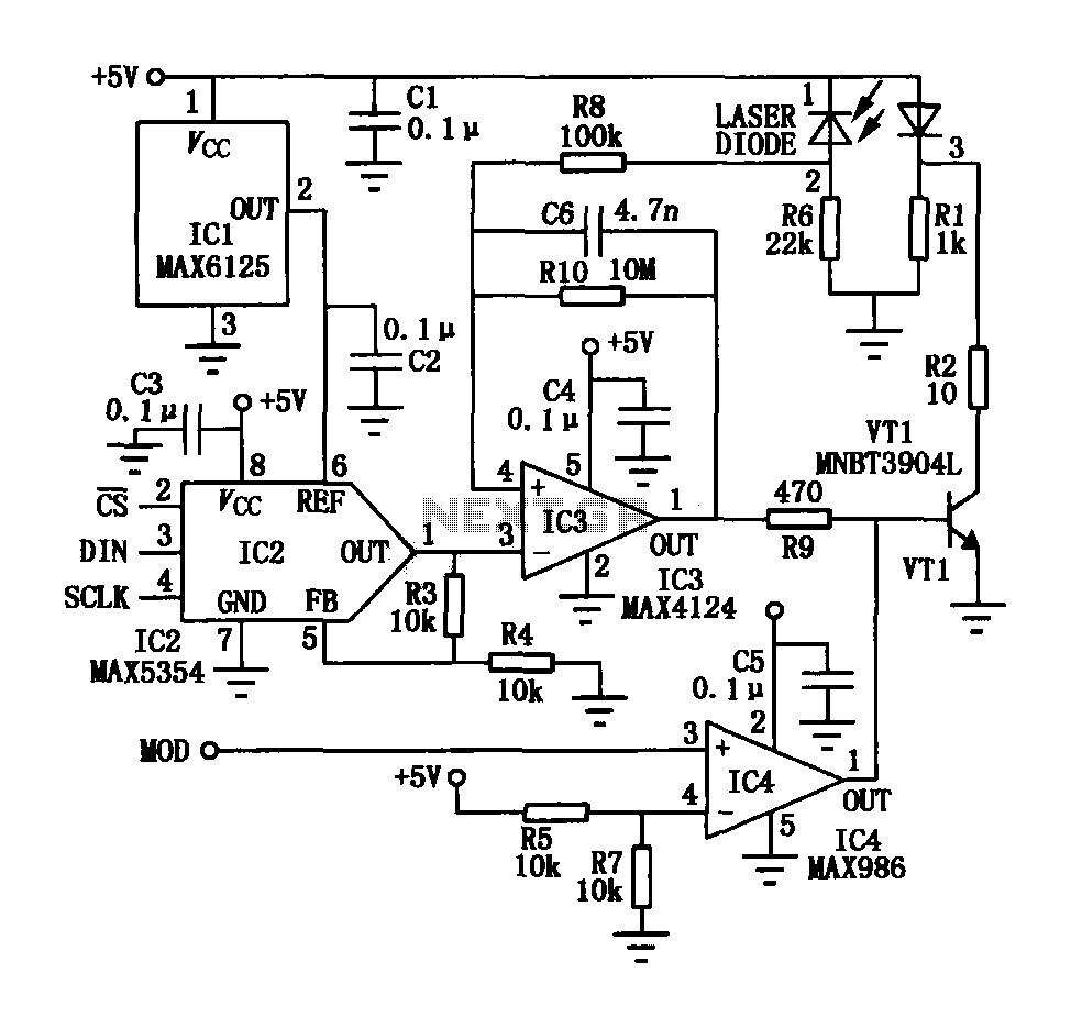
The laser tube drive circuit typically incorporates a photodiode that generates a laser beam proportional to the intensity (optical power) of the current. However, this type of photocell is generally slow and unable to track modulation effectively, particularly for...
In all the houses exist the bells in the door. All want, they have the possibility of being possible to change the intensity, the tone of sound. With this circuit we have this possibility. With the materials round the...
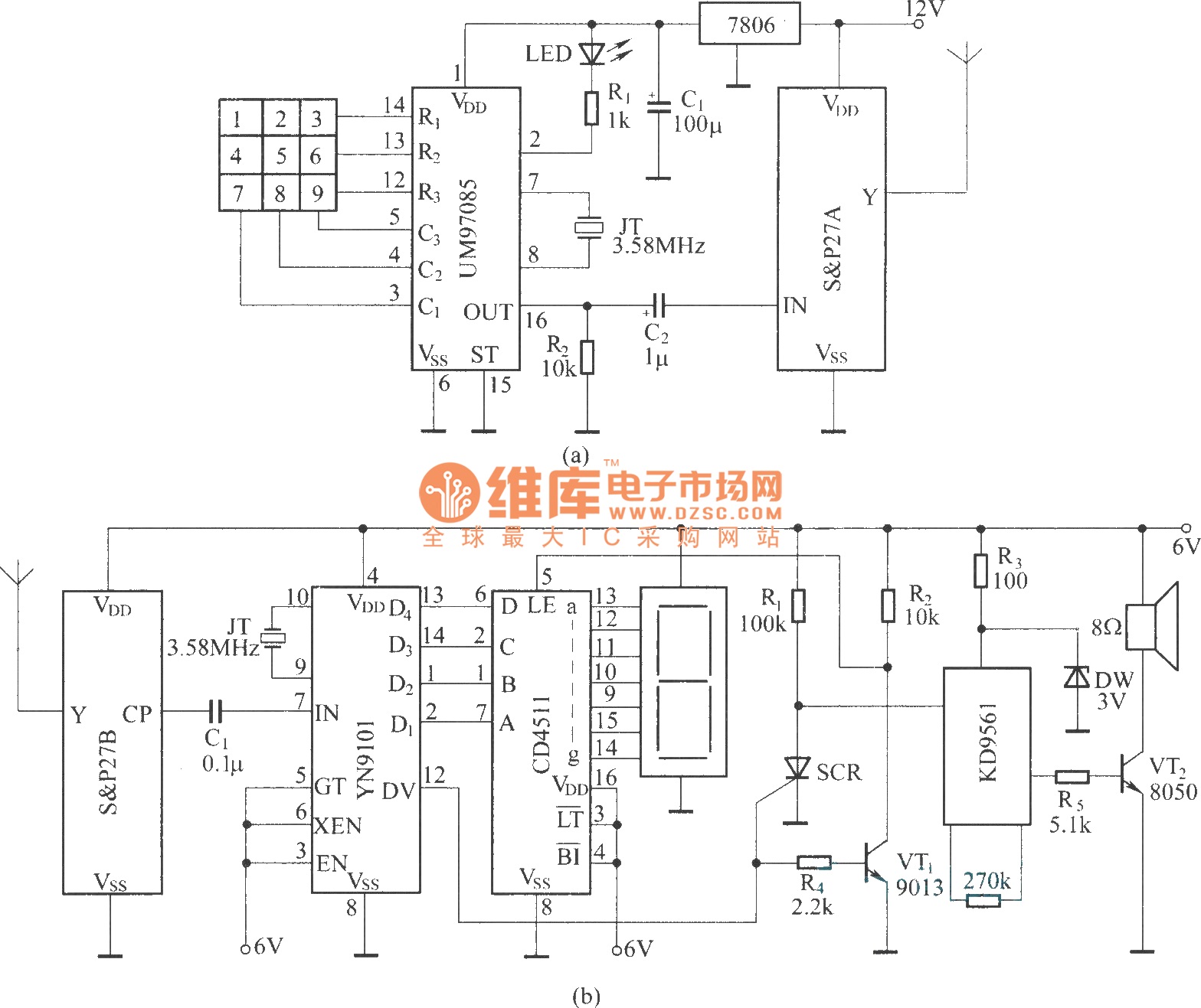
It utilizes a DTMF encoder output, which generates a dual-tone multi-frequency coded signal to modulate the transmitted carrier frequency. This configuration allows for the formation of a DTMF-encoded radio paging system. The circuit incorporates a DTMF encoding chip, UM97085,...
Motor windings are set to connect in a Y configuration while the load is active. The system includes an electric suction mechanism, and the motor is designed to operate under specific conditions. It is rated for 600 revolutions per...