
simple function generator circuit

The function generator circuit based on the LM1458 operational amplifier can generate various waveform outputs, including sine, square, and triangle waves. This versatility is achieved through the configuration of external resistors and capacitors, which determine the frequency and amplitude of the output signals.
In a typical configuration, one op-amp is used for generating the triangle wave, while the second op-amp is employed for producing the square wave. The triangle wave is created by integrating a square wave signal, which can be generated using a feedback network consisting of resistors and capacitors. The integration process causes the output to ramp up and down, producing a triangular waveform.
The square wave can be derived from the triangle wave by employing a comparator configuration within the second op-amp. This comparator switches the output state based on the threshold levels set by the reference voltages. By adjusting the resistors in the feedback loop, the duty cycle of the square wave can also be modified.
Power supply requirements for the LM1458 are typically ±15V, which allows for a wide range of output swing and ensures the operational amplifiers function effectively across various applications. The design must also consider the bandwidth and slew rate of the op-amps to ensure that the generated signals are clean and free from distortion.
In summary, the LM1458-based function generator circuit is a robust solution for generating different types of waveforms, suitable for various applications in testing and signal processing. Proper selection of external components and configurations is essential to achieve the desired performance characteristics.A simple function generator circuit using LM1458 is known here. LM1458 is a dual general purpose operational amplifier. The two opamps inside LM1458 has a common bias network, power supply line and are independent of each other in operation.. 🔗 External reference
Related Circuits

A GdS cell serves as one leg of a bridge circuit. Potentiometer R6 in another leg establishes the trip point. Potentiometer R5 allows for hysteresis adjustment to prevent chattering or hunting of the relay. The light level must increase...
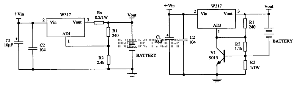
The W317 circuit integrates a three-terminal adjustable voltage regulator designed for battery charging applications. It features a constant pressure limiting charger circuit, where resistor Rs is employed to restrict the charge current, thereby reducing the initial charge rate. Additionally,...
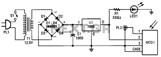
A schematic diagram for the remote analyzer is presented. The circuit is powered by a simple 5-V supply, which includes components such as PL1, SI, Tl, a bridge rectifier formed by diodes D1 through D4, capacitor CI, and a...
As the position of the sun changes, the illumination level on the light-dependent resistors (LDRs) also varies, causing the input voltage for the window comparator to deviate from half of the supply voltage. Consequently, the output of the comparator...
A basic digital voltmeter circuit utilizing the Harris Semiconductor ICL7107 is presented. It operates within a 2-V range. Calibration involves applying a known voltage of 1.2 V to the input and adjusting resistor R3 to achieve an accurate reading...
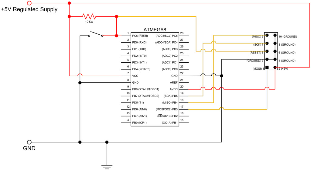
This tutorial continues from the ATmega8 Breadboard Circuit Part 1, where a small power supply was built on a breadboard. In this part, the ATmega8 microcontroller will be added along with an interface for programming. The first step is...