
Single-phase motor automatic intermittent operation control circuit

The circuit operates using the 555 timer in an astable mode, providing a square wave output that controls the bidirectional thyristor. The thyristor acts as a switch that allows current to flow to the motor during the 'on' phase of the 555 timer output. The use of a capacitive step-down circuit ensures that the voltage supplied to the motor is reduced, protecting it from overvoltage conditions and allowing for controlled operation.
The timing of the motor's operation is determined by the values of the resistors Ri and R2, as well as the capacitor C1. The relationship between these components can be described by the timing equation for the 555 timer, which dictates the duration of the high and low states in the output signal. By modifying these values, the user can achieve the desired operational characteristics of the motor, such as varying the running time or the downtime.
In practical applications, this circuit can be employed in various motor control scenarios, such as in automated systems where motors need to operate intermittently. The precise control over the motor's running and stopping times allows for efficient energy use and can enhance the overall performance of the system. The bidirectional thyristor adds versatility, enabling the circuit to control motors that may require reverse operation, depending on the application needs. Circuit shown in Figure 3-16. It uses 555 IC A as the control element; capacitive step-down circuit; bidirectional thyristor V between the motor control intermittent operation. Adjusting the resistance Ri, R2 or capacitance value Cl allows you to change the motor running and stop time. Press the icon parameters, the running time is 50s, downtime 15s.
Related Circuits
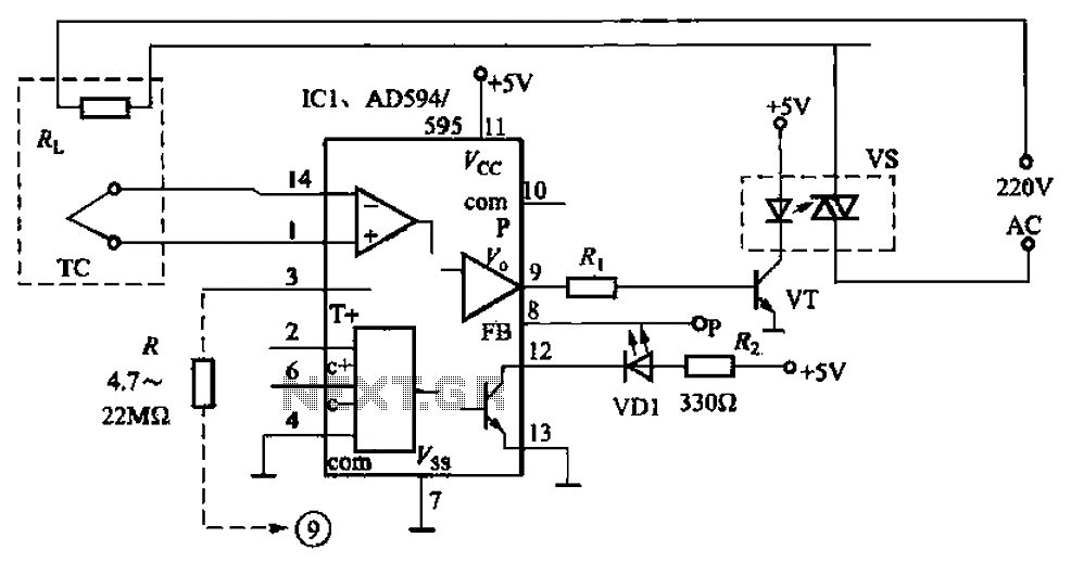
Continued from the previous post. The same principle is true for the following: temperature to current transmitter. In this case, the input voltage is proportional to the measured temperature, not the rotation. The temperature input is a full analog,...
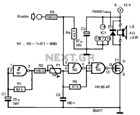
A CD4093 chip and several components form a siren oscillator that drives power MOSFET Tl. A speaker is directly powered by this device. The siren is activated by a logic high signal applied to the ENABLE input. The circuit comprises...
A rotary 3-position, 3-pole switch. In one pole, a capacitor is connected to the other pole, with no bleeding from one capacitor to another. A rotary switch with three positions and three poles is a versatile component often used in...
The tester provides an audible indication of the logic level of the signal presented to its input. A logic high is indicated by a high tone, a logic low is indicated by a low tone, and oscillation is indicated...
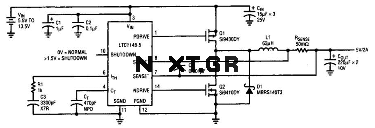
A typical LTC 1148 surface-mount application provides 5 V at 2 A from an input voltage range of 5.5 V to 13.5 V. The operating efficiency, illustrated in B, peaks at 97% and remains above 90% from 10 mA...
An automatic electric furnace temperature controller is depicted in FIG. 1-25. The closed circuit is established through a temperature detection output control loop. As the temperature rises, the output voltage increases. When the voltage reaches a preset temperature value,...