
Electric Oven automatic temperature controller

The automatic electric furnace temperature controller operates as a feedback system, utilizing a thermocouple (TC) for precise temperature measurement. The TC generates a voltage output proportional to the temperature, which is fed into an integrated circuit (IC1) that contains a differential amplifier. The differential amplifier compares the TC output voltage against a reference voltage set by an external resistor divider network. As the temperature rises, the output voltage from the differential amplifier increases until it reaches a threshold level defined by the set point. At this juncture, the output to the solid-state relay (VT) is interrupted, effectively stopping the heating process.
The solid-state relay is employed for its rapid switching capabilities and durability compared to mechanical relays. It connects to the heating element (RL), which is typically a resistive load. As the temperature drops below the set point, the TC's voltage output decreases, prompting the differential amplifier to reactivate the solid-state relay, thus restarting the heating cycle.
The hysteresis feature, adjustable via the resistor (R), prevents rapid cycling of the heating element by introducing a temperature band within which the system will not react to minor fluctuations. This is crucial for maintaining a stable temperature and prolonging the lifespan of the heating element and relay.
The controller also integrates alarm functionality through designated pins, which can signal the status of the system. The open transistor configuration allows for direct interfacing with visual or auditory indicators, such as LEDs or buzzers, enhancing user awareness of the system's operational state. The inclusion of a zero offset circuit in the AD594/595 may provide additional calibration capabilities, ensuring accurate temperature readings under varying conditions, although it is not utilized in this specific design.
Overall, the automatic electric furnace temperature controller exemplifies an efficient and reliable method for managing heating processes, suitable for various industrial and laboratory applications. Automatic electric furnace temperature controller shown in FIG. 1-25. The closed circuit is formed from a temperature detection output control loop; the temperature rises, the output voltage increases when the voltage increases to a preset temperature value, the output stop, stop heating; trans, the temperature is lowered, when reduced to the pre when the set temperature, and automatically starts heating. TC thermocouple directly connected to IC1 s O, ? feet, sending internal differential amplifier, the output from a foot, driven by solid state relay vs VT conduction, plus hot wires RL ohmic heating, when heated to a preset temperature, output is stopped.
pin input and output hysteresis setting, connected to a pin through resistor R to achieve, the smaller the resistance value, the greater the hysteresis. Controlling the temperature of the high and low foot by pressing decisions relations pin voltage and temperature, TC between as shown in Table 1-3.
AD594/595 is also designed with zero offset circuit (not used here). ?, ? pin alarm, indicating the output of the internal as c, e very open transistor can directly drive LED or small relays, access here VD1 as the working lights for indicating the start and stop on heating.
Related Circuits
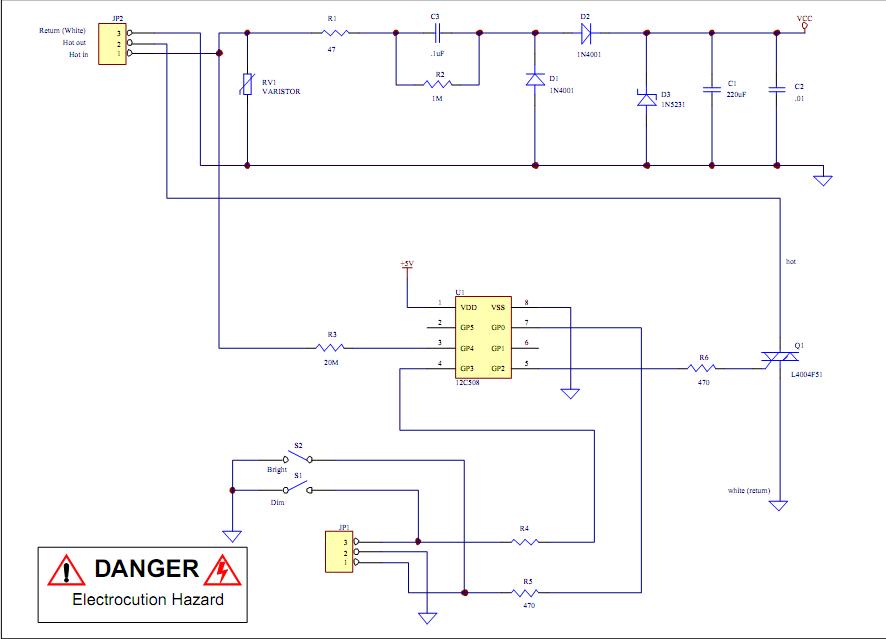
Assistance is required to modify a light dimmer circuit connected to a PIC12C508 microcontroller. This circuit is designed for the... The light dimmer circuit utilizing the PIC12C508 microcontroller serves to control the brightness of a light source through pulse width...

Personal safes are innovative locking storage solutions that open with a simple touch of a finger. These devices are designed as secure storage options for medications, jewelry, firearms, documents, and other valuable or potentially hazardous items. They employ fingerprint...
The circuit is a small temperature regulator that warns for an increase in temperature. The control of temperature comes from the thermistor TH1, which has a negative temperature coefficient. Its resistance varies from approximately 10K ohms at 25°C to...
A buzzer circuit utilizes a PIC microcontroller to drive a piezo buzzer. The microcontroller is a low-power processor that is ideal for portable and compact devices where battery conservation is essential. The buzzer circuit employs a PIC microcontroller, which serves...
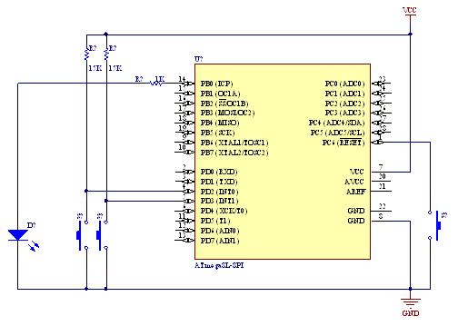
A demonstration of external interrupts in the AVR (Atmega8) microcontroller, including a circuit diagram and C code for the interrupt service routine (ISR). The Atmega8 microcontroller is a versatile device widely used in embedded systems, particularly for applications requiring external...
The liquid level controller circuit comprises a power supply circuit and a level detection control circuit, as illustrated in the accompanying chart. The power supply circuit includes a power switch (S1), a power transformer (T), bridge rectifiers (UR1, UR2),...