
Audible Logic Tester Circuit

The described circuit functions as a logic level tester, providing clear audio feedback regarding the state of digital signals. The high-impedance input allows for minimal interference with the tested circuit, ensuring accurate troubleshooting of TTL (Transistor-Transistor Logic) and CMOS (Complementary Metal-Oxide-Semiconductor) logic families.
The core of the circuit utilizes an LM339 quad comparator, which features four independent comparators. In this application, two of these comparators (IC1-a and IC1-b) are configured to establish voltage thresholds. IC1-a activates when the input voltage surpasses 67% of the supply voltage, signaling a logic high, while IC1-b activates when the input voltage falls below 33%, indicating a logic low. Resistors R1 and R2 are strategically placed to prevent false triggering of the comparators when the input is floating or within the undefined voltage range between the set thresholds.
The output from the comparators controls two gated astable multivibrators, implemented using additional sections of the LM339. The high tone generator, composed of IC2-a and IC2-b, is responsible for producing an audible high-pitched tone when a logic high is detected. Conversely, the low tone generator, utilizing IC2-c and IC2-d, emits a lower frequency tone for logic low signals.
To ensure that the outputs of the tone generators do not interfere with each other, diodes D1 and D2 are employed to isolate the signals. This isolation prevents any backflow of current that could distort the tones produced. The final output is amplified through transistor Q1, which drives a low-impedance speaker, allowing for clear and audible indications of the logic levels.
This tester is particularly useful in educational settings and practical applications where quick and reliable assessment of logic states is necessary. Its design emphasizes simplicity and effectiveness, making it an essential tool for engineers and technicians working with digital circuits. The tester provides an audible indication of the logic level of the signal presented to its input. A logic high is indicated by a high tone, a logic low is indicated by a low tone, and oscillation is indicated by an alternating tone. The input is high impedance, so it will not load down the circuit under test. It can be used to troubleshoot TTL or CMOS logic. The input section determines whether the logic level is high or low, and enables the appropriate tone generator; it consists of two sections of an LM339 quad comparator.
One of the comparators (ICl-a) goes high when the input voltage exceeds 67% of the supply voltage. The other comparator goes high when the input drops below 33% of the supply. Resistors Rl and R2 ensure that neither comparator goes high when the input is floating or between the threshold levels. The tone generators consist of two gated astable multivibrators. The generator built around IC2-a and lC2-b produces the high tone. The one built around IC2-c and IC2-d produces the low tone. Two diodes, 1 and 1)2, isolate the tone-generator outputs. Transistor Ql is used to drive a low-impedance speaker.
Related Circuits

This design circuit is intended for sine wave oscillators, providing both sine and square wave outputs across a frequency range from below 20 Hz to above 20 KHz. The oscillation frequency can be easily adjusted by changing a single...
This is a simple proximity switch utilizing the IC 4049. The IC 4049 is a bipolar monolithic integrated circuit designed for metal detection systems and proximity sensing applications. It includes an oscillator formed by an external parallel resonant tank...
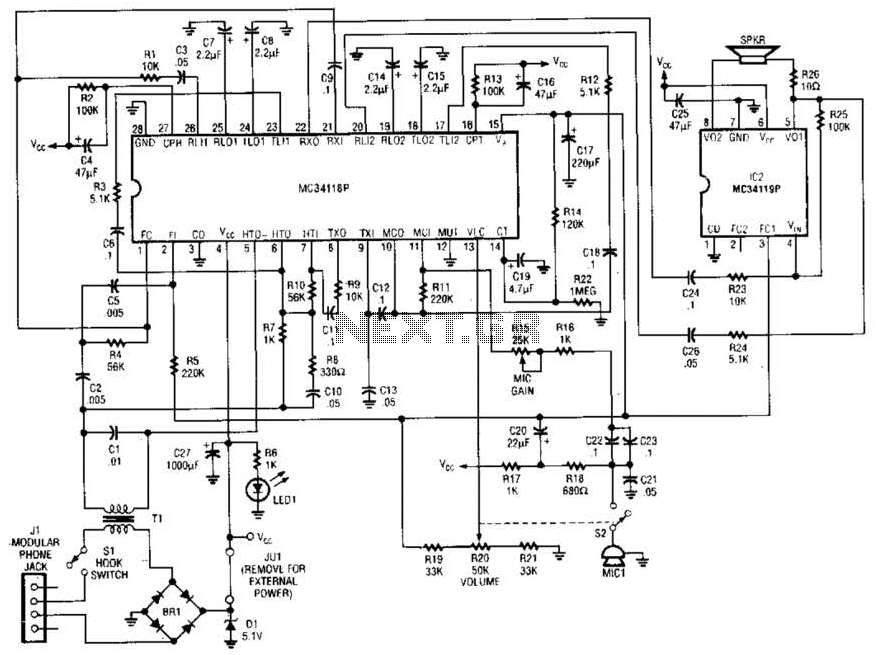
Using a Motorola MC34118 speakerphone IC, this adapter can be utilized with a standard telephone to enable speaker functionality. The device is powered from the phone line; however, it can also be powered through an external power supply if...
This circuit enables the switching on and off of appliances through telephone lines. It allows for the control of appliances from any distance, overcoming the limitations of infrared and radio remote controls. The circuit can manage up to nine...
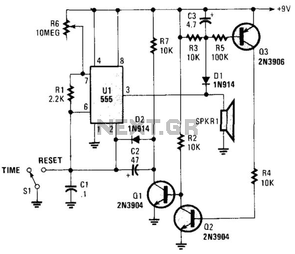
This circuit operates in astable mode and produces a tone at the end of the first period, which can last several minutes. When switch SI is in the time position, transistor Q3 is turned off because pin 3 of...
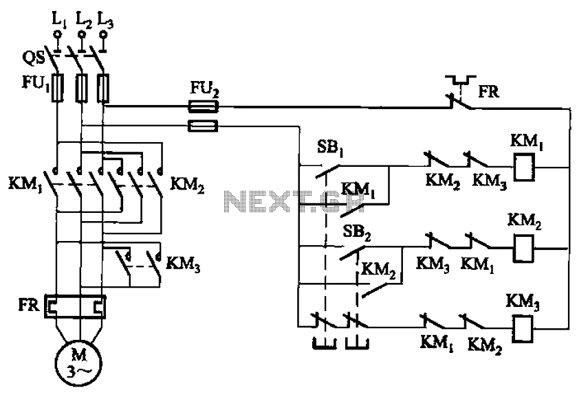
The circuit depicted in Figure 3-154 illustrates the KM3 braking contactors. During shutdown, the system can disconnect the operating system. At this point, KM3 activates, causing its normally open contact to close, thereby shorting the three-phase stator windings to...