
A typical electronic volume control circuit

The electronic volume control circuit typically involves several key components that work together to manage audio levels effectively. At its core is the TC9211P integrated circuit, which serves as the digital-to-analog converter (DAC) and the volume control processor. This IC receives digital control signals from the CPU, which dictate the desired volume level. The control signals include clock, data, and standby signals that are essential for the operation of the TC9211P.
The interface circuit plays a crucial role in facilitating communication between the CPU and the TC9211P. It ensures that the digital signals are correctly formatted and transmitted, allowing for accurate decoding. The input pins of the circuit receive stereo audio signals, which are typically in the form of differential signals to minimize noise and interference. These signals are then processed by the TC9211P, which adjusts the amplitude of the audio signals based on the control signals received.
The output pins deliver the adjusted analog audio signals to the audio amplification stage or directly to the speakers. This allows the user to experience varying audio levels based on their preferences. The circuit may also incorporate additional features such as mute functionality and a standby mode to enhance usability and energy efficiency.
Overall, the electronic volume control circuit is an essential component in modern audio systems, providing precise and reliable control over sound levels in stereo applications. Its integration with digital systems, such as CPUs, reflects the increasing convergence of analog and digital technologies in audio processing.A typical electronic volume control circuit It shows a typical electronic volume control circuit. The circuit is often used in stereo audio devices through the computer (CPU) i nto the line and adjust the volume control. Stereo signals by the, ? pin input by, pin output adjusted. The control signal to the CPU (clock, data and standby) from ? ~ foot into TC9211P in via an interface circuit for decoding and D/A converter into an analog signal control input signal amplitude number, so as to achieve the purpose of controlling the volume .
Related Circuits
A simple CATV upstream fiber optic receiver utilizes DC pilot automatic gain control (AGC). Upstream fiber links in a community antenna television (CATV) system are often challenging to align correctly. Set-top boxes and cable modems use "long-loop" AGC. Additionally,...
The concept involves mounting a microphone on a stick with an LED and designing a circuit that responds to loud noises detected by the microphone input (such as blowing) to turn off the LED. The schematic is straightforward, powered...
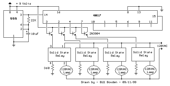
This circuit is fundamentally similar to the channel LED sequencer, with the enhancement of solid-state relays for controlling AC lamps. The relay depicted in the diagram is a Radio Shack 3 amp unit (part no. 275-310), which requires 1.2...
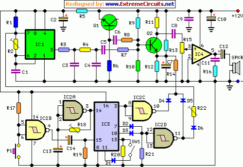
This circuit generates a two-tone effect similar to the cuckoo song. It can be utilized for doorbells or other applications due to its integrated audio amplifier and loudspeaker. As a sound effect generator, it can connect to external amplifiers,...
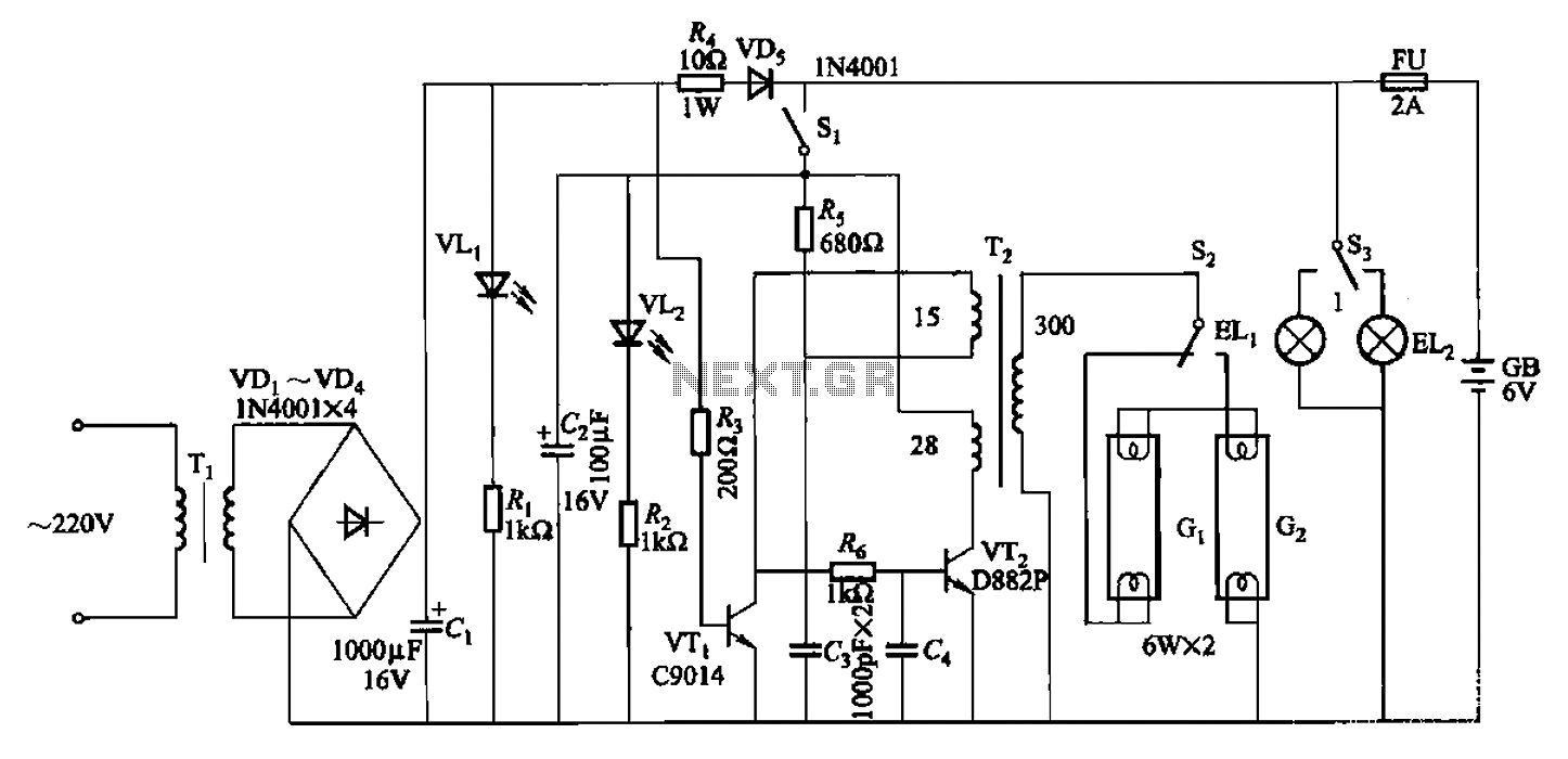
The 786A multi-functional double-tube fluorescent emergency circuit is illustrated in Figure 2-129. This circuit shares similarities with Figure 2-125. The 786A multi-functional double-tube fluorescent emergency circuit is designed to provide illumination during power outages or emergencies. It utilizes two fluorescent...
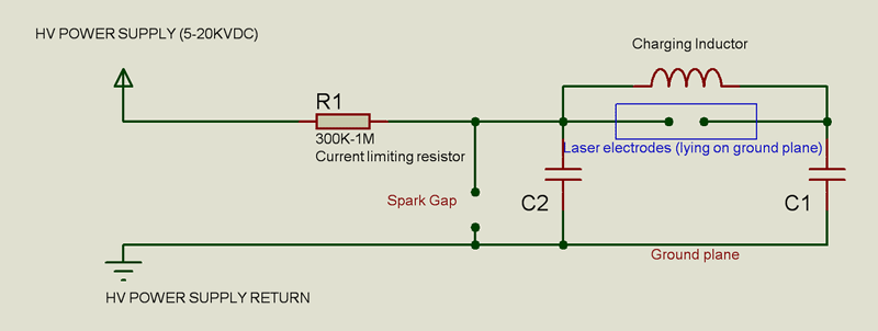
This laser is constructed on a polystyrene sheet. An aluminum foil layer acts as a ground plate (-), which is important for preionization. After that, the dielectric is placed on it, leaving 1 cm from each border of the...