
under?-over voltage detector
Part List
R1=2Kohm/V minus 10Kohm R6-11=2.2Kohm D3-5=1N4001
R2-9-10=1Kohm R7-12=4.7Kohm D4=3V3 0.5W Zener
R3-8=10Kohm RV1-2=10Kohm pot. IC1-2=LM741
R4=1.2Kohm D1=6V8 0.5W Zener Q1-2=BC214
R5=47Kohm D2=5V6 0.5W Zener RL1-2=12V >120ohm Relay
The circuit described is a precision DC undervoltage relay switch utilizing an operational amplifier (op-amp) configured as a voltage comparator. In this configuration, the op-amp compares the voltage at its inverting input (pin 2) with the voltage at its non-inverting input (pin 3). When the voltage at pin 3 exceeds the reference voltage at pin 2, the output of the op-amp switches high, activating the relay (RL1-2). The relay is designed to operate at voltages exceeding 5 volts, with the exact trip point adjustable through the resistor R1.
For over-voltage detection, the circuit allows for trip points as low as 10 mV to 3 volts when the input voltage is applied directly to pin 2. For input voltages greater than 3 volts, a range resistor must be included to ensure that the voltage at pin 2 remains within the operational limits of the op-amp. The design also incorporates the flexibility to convert the circuit into an undervoltage switch by swapping the connections of pins 2 and 3.
To enable the circuit to work with AC voltage signals, an additional rectification stage is required to convert the AC input into a suitable DC voltage. This modification allows for broader applications of the circuit in various voltage monitoring tasks.
The part list provided includes various resistors (R1 to R7), potentiometers (RV1-2), zener diodes (D1 to D4), a rectifier diode (D3-5), transistors (Q1-2), and the relay (RL1-2), which are critical for ensuring the correct functionality and reliability of the circuit. The LM741 op-amp is the core component, providing the necessary voltage comparison capabilities. The specified values for the components allow for precise tuning of the voltage thresholds, making this circuit suitable for various applications in voltage monitoring and control systems. In Fig.1 A precision DC under?voltage relay switch. The opamp is wind as a voltage comparator, with a reference voltage applied to pin 2 and the test voltage applied to pin 3: the relay turns on when the pin 3 voltage exceeds that of pin 2. The circuit can be made to trip at any voltage in excess of 5 volts by suitable choice of R1 value. In Fig. 2 An over-voltage switch that can be used to trip at any pre-set voltage in excess of about 10 mV. The input voltage can be connected directly to pin 2 if trip values in the range 10mV to 3Volts are required.
For voltages in excess of 3 Volts, a suitable range resistor must be connected in the position shown, to keep the pin 2 Voltage drive to suitable level. The circuit can be converted to an under?voltage switch by transposing the pin 2 and pin 3 connections of the op-amp.
The circuit can be used as an AC voltage switch by first rectifying the AC input signal. Part List R1=2Kohm/V minus 10Kohm R6-11=2.2Kohm D3-5=1N4001 R2-9-10=1Kohm R7-12=4.7Kohm D4=3V3 0.5W Zener R3-8=10Kohm RV1-2=10Kohm pot. IC1-2=LM741 R4=1.2Kohm D1=6V8 0.5W Zener Q1-2=BC214 R5=47Kohm D2=5V6 0.5W Zener RL1-2=12V >120ohm Relay
🔗 External reference
Related Circuits
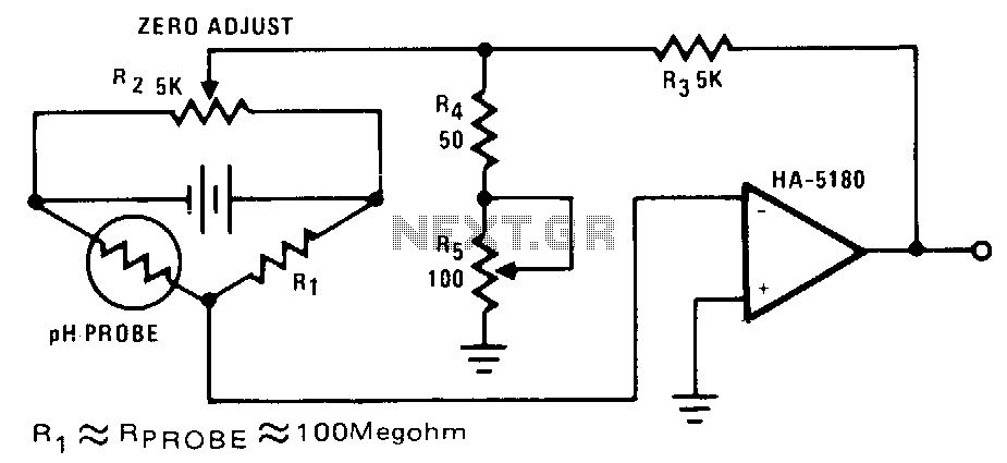
The highest sensitivity is attained when R1 is roughly equal to the probe resistance. The circuit can be calibrated to zero using R2, while R5 regulates the full-scale voltage. The relationship between pH and output voltage may not be...
Dark Detector with LM555. This is a dark detector circuit that generates sound in the absence of a light source and remains silent when light falls on the CdS (Cadmium Sulfide) sensor. The dark detector circuit utilizes the LM555 timer...
This voltage-to-frequency converter (VFC) circuit utilizes a 555 integrated circuit (IC) and a 741 operational amplifier (op-amp) as its primary components. The circuit is capable of generating oscillations of up to 20 kHz. The voltage-to-frequency converter circuit is designed to...
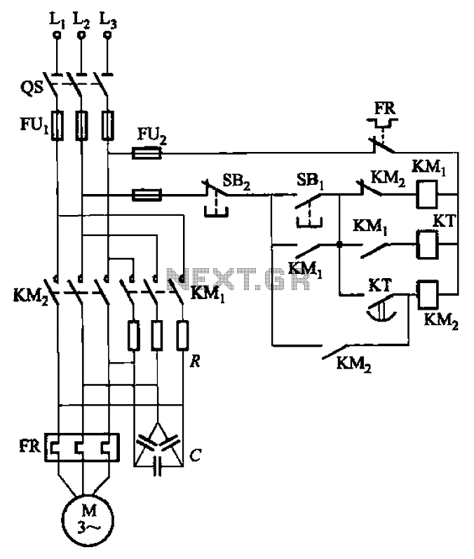
The circuit depicted in Figure 3-35 demonstrates a method for starting a motor that transitions to full voltage through a step-down switching process. This approach provides an uninterruptible power supply, effectively preventing issues related to switching currents that may...
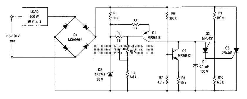
The circuit is an open-loop RMS voltage regulator designed to deliver 500 watts of power at 90 V RMS, maintaining good regulation within an input voltage range of 110-130 V RMS. When the input voltage is applied, capacitor C1...

A stable voltage source can be generated by amplifying a stable voltage reference. The LM10 component provides both the reference and the amplification. The LM10 is a precision voltage reference and amplifier integrated circuit that is designed to produce a...