
90Vrms voltage regulator

The open-loop RMS voltage regulator circuit operates by utilizing a combination of capacitors, resistors, and transistors to maintain a stable output voltage despite variations in input voltage. The primary components include capacitor C1, which plays a critical role in timing the activation of Q3, a key transistor that regulates the circuit's operation. The charging of C1 is influenced by the input voltage, and its charge level determines when Q3 will fire.
Resistor R10 is crucial for sensing the input voltage; as the input voltage increases, the voltage drop across R10 increases, which effectively raises the threshold for Q3's activation. This feedback mechanism ensures that the output voltage remains stable by adjusting the timing of Q3's firing in response to input voltage fluctuations.
Transistor Q5 serves as the main switch that controls the flow of current to the load. When Q3 is activated, it turns on Q5, allowing current to pass through and power the connected load. The circuit's design ensures that as the input voltage increases, the delay introduced by the increased firing point of Q3 compensates for the higher input, maintaining a consistent output voltage.
In scenarios where the input voltage decreases, the feedback loop operates in reverse. The voltage across R10 decreases, lowering the firing point of Q3, which allows for quicker activation of Q5, thus maintaining the output voltage within the desired range. This dynamic response to input voltage changes highlights the circuit's robustness and effectiveness in providing regulated power output.
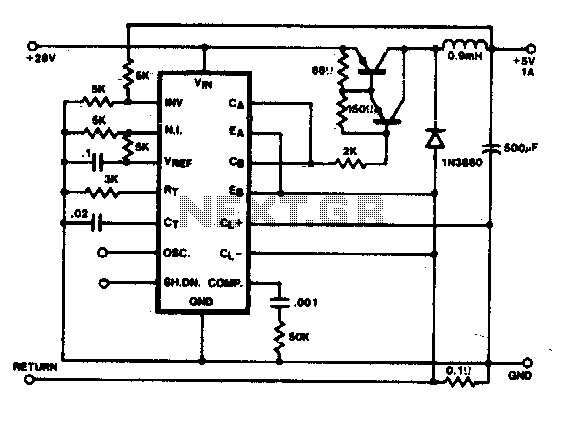
Overall, this open-loop RMS voltage regulator circuit is an efficient solution for applications requiring stable voltage levels, particularly in environments where input voltage may vary significantly. The careful selection of components and their arrangement within the circuit contributes to its performance and reliability in delivering consistent power.The circuit is an open loop rms voltage regulator that will provide 500 watts of power at 90 V rms with good regulation for an input voltage range of 110-130 V rms. With the input voltage applied, capacitor Cl charges until the firing point of Q3 is reached causing it to fire.
This turns Q5 on which allows current to flow through the load. As the input voltage increases, the voltage across R10 increases which increases the firing point of Q3. This delays the firing of Q3 because Cl now has to charge to a higher voltage before the peak-point voltage is reached.
Thus the output voltage is held fairly constant by delaying the firing of Q5 as the input voltage increases. For a decrease in the input voltage, the reverse occurs.
Related Circuits
The project encompasses both hardware and software design for a 12/24V DC 20A charge controller suitable for solar, wind, hydro, or pedal power applications. This initiative aims to create an open-design, cost-effective, yet fully functional charge regulator for renewable...
Although the 78xx series of voltage regulators are available with different current outputs, you can boost the available current output with this circuit. A power transistor is used to supply extra current to the load, maintaining a constant voltage....
In this conventional single-ended regulator circuit, the two outputs of the SG1524 are connected in parallel for effective 0-90% duty-cycle modulation. The use of an output inductor requires an RC phase compensation network for loop stability. The described circuit utilizes...
This circuit utilizes an LM339 quad voltage comparator to create a time delay and manage a high current output at low voltage levels. Approximately 5 amps of current can be achieved using two fresh alkaline D batteries. Three of...
This simple low voltage tester circuit can be used to monitor batteries and other voltage sources for issues, utilizing an LED display and alarm sound. The low voltage tester circuit is designed to provide a reliable method for monitoring the...
In a hybrid system, an analog system with digital control, voltage-controlled components are crucial as they can be interfaced with a Digital-to-Analog Converter (DAC) from the digital system. In hybrid systems, the integration of analog and digital components allows...