
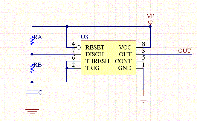
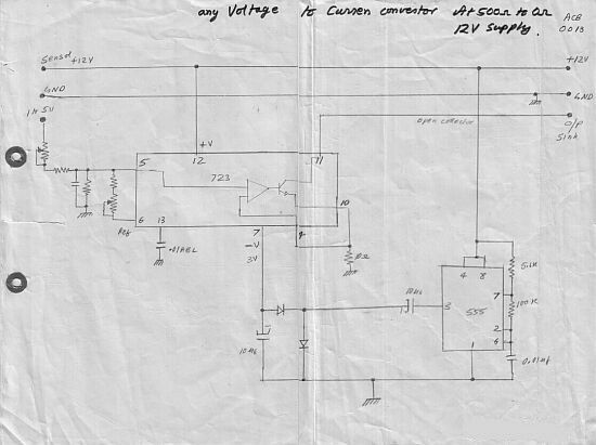
voltage to frequency converter with 555

The voltage-to-frequency converter circuit is designed to convert an input voltage into a corresponding frequency output. The configuration employs the 555 timer in astable mode, which allows it to generate a continuous square wave output. The frequency of this output is primarily determined by the values of the resistors and capacitors connected to the 555 timer.
In this circuit, the 741 op-amp is used to buffer the input voltage, providing a stable reference for the 555 timer. The op-amp configuration can be set up as a non-inverting amplifier, ensuring that the input voltage does not load the source and that the output remains linear over the desired voltage range.
The frequency output from the 555 timer can be calculated using the formula:
\[ f = \frac{1.44}{(R1 + 2R2)C} \]
where \( R1 \) and \( R2 \) are the resistances connected to the 555 timer, and \( C \) is the capacitance. By selecting appropriate values for \( R1 \), \( R2 \), and \( C \), the circuit can be tuned to generate frequencies up to 20 kHz based on the input voltage levels.
Additionally, the circuit may include a diode for discharge purposes, ensuring that the timing capacitor discharges quickly, which is essential for maintaining stability in the frequency output. The output can be connected to a frequency counter or other measuring devices to visualize the frequency changes in response to varying input voltages.
This VFC circuit is applicable in various fields, including signal processing, data acquisition systems, and frequency modulation applications, where precise frequency generation from a voltage level is required.This voltage to frequency converter (VFC) circuit uses 555 IC and 741 op-amp as the main components. Up to 20kHz oscillation can be produced by this circuit 🔗 External reference
Related Circuits

This is a simple smoke alarm circuit using a timer IC, the NE555. The circuit operates by illuminating a Light Dependent Resistor (LDR) with a lamp. When smoke obscures the light from the lamp, the resistance of the LDR...
This calculator computes the resistor and capacitor values for a NE555 timer chip configured as an astable multivibrator (oscillator) or square wave generator. By entering the desired duty cycle and frequency, the calculator provides suitable values for the resistors...
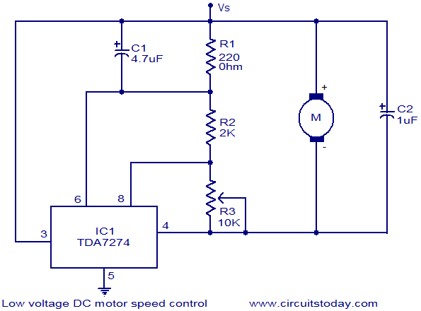
The circuit diagram illustrates a low voltage/low power DC motor speed controller utilizing the TDA 7274 integrated circuit from ST Microelectronics. The TDA 7274 is designed for low voltage and low power applications, featuring an internal voltage reference, a...
This amplifier can transfer DC to 5 MHz signals across a potential difference of 25,000 V. It can be utilized in CRT displays and high-voltage applications. It is important to note that the tube must be shielded due to...
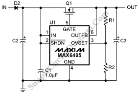
To protect downstream circuits from overvoltage conditions that occur during load-dump events or transients, the MAX6495, MAX6499, MAX6397, and MAX6398 can be utilized. The MAX6495, MAX6499, MAX6397, and MAX6398 are integrated circuits designed for overvoltage protection in various electronic applications....
This circuit converts a voltage control output from a process controller into a current control signal, which is necessary when an AC drive or valve requires a current control signal. It operates as a three-wire voltage-to-current loop converter. A...