
Multi-point circuit diagram of a remote control switch

The circuit operates by first converting the AC input voltage to a regulated DC output using the buck rectifier. This rectifier is crucial for providing a stable 13V DC supply to the subsequent control circuitry. The 555 timer is configured in a bistable mode, allowing it to toggle between two states based on input signals from the switches (K1, K2, or Ks). The flip-flop behavior is established through the charging and discharging cycles of capacitors C1 and C2, influenced by the resistors R4, R5, and R13.
In the initial state, with C1 charged, the 555 timer is set to a high state. Pressing the control switch (K1, K2, or Ks) causes C1 to charge quickly, triggering a transition in the 555 timer. This transition generates a low output at pin 3, effectively turning off the SCR, which in turn cuts off the voltage to the load (VT). The feedback mechanism involving pin 6 of the 555 timer ensures that the circuit remains stable in its reset state until the next activation occurs.
This design allows for efficient control of electrical devices, providing the ability to turn them on or off remotely. The use of a thyristor for switching enhances the circuit's capacity to handle higher loads, making it suitable for various applications in automation and remote control systems. The careful selection of component values (R and C) determines the timing characteristics and responsiveness of the control circuit, allowing for customization based on specific requirements.As shown, the switching circuit comprises a buck rectifier circuit, the bistable trigger circuit and the thyristor control circuit. Implement remote control for electrical equipment turned on or off. Buck rectifier circuit provides the controller with a DC voltage of 13V. 555 and R5, R4, R13, C1, C2 and so flip-flop circuit. Just power, because the voltage on C1 is not mutation, 555 set, C2 through R5 charged to l2V. If you click this time K1 (K2 or Ks), C1 is quickly charged to a 2/3 VDD = 8V, 555 reset pin 3 referred to the low level, SCR off. Meanwhile, VT cut-off, 555 were 6 feet high, so that the reset 555 in a stable state. As then click K1 (K2 or Ks), and 555 is in the set state. So control K, can be realized on the electrical opening and closing control.
Related Circuits
Ultrasonic Switch. A circuit of a new type of remote control switch is described here. This circuit operates with inaudible sound waves. The ultrasonic switch operates by utilizing ultrasonic frequencies, which are sound waves above the range of human hearing...

A simple audio watt meter circuit or an audio power or audio level meter circuit with diagram and schematics to measure amplifier audio output power in watts. The audio watt meter circuit is designed to measure the output power of...
This single transistor audio mixer is utilized in an amplifier circuit design featuring a base-driven transistor, with its emitter being current-controlled. This audio mixer circuit employs a single transistor to facilitate the mixing of audio signals. The transistor operates in...
This PWM controller circuit is suitable for managing small motors with a maximum current consumption of 2A. For higher currents, additional cooling is required. The PWM (Pulse Width Modulation) controller circuit is designed to efficiently control the speed of small...
This circuit can be utilized as a replacement for the single current-limiting resistor typically found in inexpensive battery chargers. The alternative presented here will prove beneficial over time, as it eliminates the need to discard NiCd batteries after a...
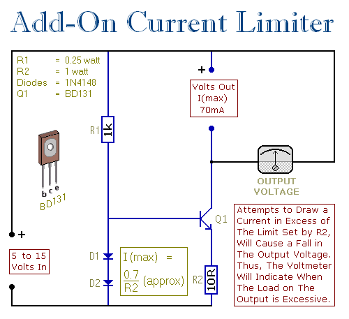
This circuit allows setting a limit on the maximum output current from a power supply unit (PSU). It is particularly useful when powering up a project for the first time or conducting a soak test. By establishing an upper...