
Automobile Lights-On Reminder

The circuit operates by monitoring the state of the vehicle's ignition and headlight system. The 2N1305 transistor functions in a switching mode, where it is normally in the off state when the ignition is active. This is achieved through a biasing arrangement that ensures the transistor does not conduct current, thus keeping the alarm system inactive.
When the ignition is turned off, the biasing condition of the transistor changes, allowing it to conduct. This conduction activates the output device, which can either be a Sonalert tone generator that emits a sound warning or a small 12-V lamp that provides a visual alert. The choice of output device depends on the design requirements and user preference.
The circuit's design is relatively simple, relying on the characteristics of the 2N1305 transistor to effectively switch the alarm system based on the vehicle's ignition state. The integration of a Sonalert or lamp provides flexibility in alerting the driver, ensuring that they are aware of the headlights being left on, which could otherwise lead to battery drain.
Overall, this circuit serves as a practical solution for enhancing vehicle safety by preventing unintended battery depletion due to the headlights being left on after the ignition has been turned off. The circuit can be used to give a visible or an audible warning that the headlights are on. It uses a 2N1305 transistor as a switch to turn on a Sonalert tone generator or a small 12-V lamp. Operating current for the transistor is supplied from the wire that feeds the headlights. When the ignition is on, the transistor is biased off and the alarm is not activated. Turning off the ignition while the lights are on sets off the alarm.
Related Circuits

The automobile interior lights fader circuit diagram is designed to gradually brighten and dim the interior lights of older vehicles. This circuit utilizes the LM324 low-power operational amplifier as its core component. The automobile interior lights fader circuit is an...

When the ignition switch is activated, relay K1 receives continuous power, allowing the headlights to be turned on. When the ignition is turned off, timer IC1 is activated, maintaining its power for a duration determined by resistor R1 and...

The circuit for a car wiper speed controller allows for adjustable wiper speed, ranging from one to ten cycles per second. This feature enables flexibility in operation and contributes to energy efficiency. The car wiper speed controller circuit typically employs...

A simple and safe white LED driver circuit has been designed for use in 12V automobiles, allowing for the efficient operation of standard high-efficiency white LED modules powered by automotive battery systems. The circuit utilizes a fixed voltage regulator...
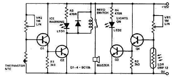
This electronic project circuit diagram for an ice warning and lights reminder system alerts drivers when their vehicle lights should be activated and warns them if the outside temperature approaches zero degrees Celsius. The system employs an LED indicator...

This is a simple circuit that can be used as a sequential signal light in automobiles. The circuit is based on two integrated circuits (ICs): a TS 555 CN CMOS timer IC and a CD4017 decade counter IC. The...