
Automobile White LED Light

To design a circuit capable of driving high-efficiency white LED modules without a dedicated buck converter or driver IC, a simple yet effective approach can be utilized. The circuit can be based on a linear regulator or a resistor-based current limiting method, depending on the specific requirements of the LED modules and the available battery voltage.
In this configuration, the power supply is connected directly to the LED modules. A current-limiting resistor must be calculated and placed in series with the LEDs to ensure they operate within their specified forward current ratings. The resistor value can be determined using Ohm's law, considering the supply voltage, the forward voltage drop of the LEDs, and the desired forward current.
For example, if the supply voltage is 12V, the forward voltage drop of the white LEDs is 3V, and the desired forward current is 20mA, the resistor value can be calculated as follows:
1. Determine the total voltage drop across the resistor:
V_R = V_supply - (number of LEDs × V_LED)
V_R = 12V - (3 LEDs × 3V) = 3V
2. Calculate the resistor value using Ohm's law (R = V/I):
R = V_R / I = 3V / 0.02A = 150Ω
In this example, a 150Ω resistor would be required. It is important to select a resistor with an appropriate power rating to handle the power dissipation, which can be calculated using P = I²R.
For applications requiring more precise current control or where the supply voltage may vary significantly, a linear regulator can be employed. The linear regulator will maintain a constant output voltage, allowing for consistent LED performance. The selection of the linear regulator should consider the maximum input voltage, output current requirements, and thermal performance.
In summary, this circuit design allows for the effective use of battery power to drive high-efficiency white LED modules without the need for specialized driver ICs, making it suitable for various applications where simplicity and cost-effectiveness are essential.Without any dedicated buck converter/white LED driver IC, you can safely drive many standard Hi-efficieny white LED modules using the battery power availab.. 🔗 External reference
Related Circuits

The circuit is an easy-to-build and use general-purpose Big LED with SPI serial interfacing. It is expandable for multiple digits while utilizing only three wires to receive data from any microcontroller boards. The design incorporates a serial-in-parallel-out shift register,...
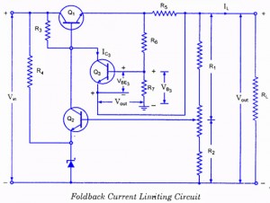
If the load resistance (RL) is reduced or the load terminals are accidentally shorted, a very large load current will flow, potentially damaging the pass transistor (Q1), diode, or other components. Fuse protection may not be sufficient, as the...
Purchase a 1W white LED and utilize a mobile phone battery to create a small lamp. A lampshade can be made from a glass-like milky white plastic bottle. The LED emits light through a radiating plate, which has two...
The IC1 is a 555 timer IC connected for astable operation. The clock pulses are fed to the IC2 via the 10K resistor. The IC2 is a 10-stage counter; output 6 (pin 5) is connected to RESET (pin 15),...
The power failure light that I eventually designed and built is housed in the plastic case from a wall-mounted power transformer. I had accidentally destroyed the transformer by shorting its output, and had kept the plastic case for years,...
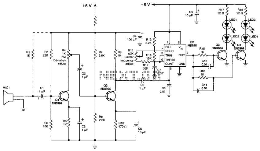
This transmitter employs a two-stage amplifier configuration using transistors Q1 and Q2 to frequency modulate an NE555 timer, which is set up as a voltage-controlled oscillator (VCO) operating at approximately 50 kHz. The resulting frequency-modulated pulse train is transformed...