
SPI Interface Big 7-Seg LED

The circuit utilizes the 74HC595 shift register, which is a widely used component for serial-to-parallel data conversion. This allows for efficient control of multiple LEDs while minimizing the number of required input/output pins on the microcontroller. The SPI interface provides a straightforward method for data transmission, ensuring that the microcontroller can easily communicate with the shift register.
The design is modular, allowing for the addition of more digits by daisy-chaining multiple 74HC595s. Each additional digit can be controlled by connecting the QH output of one shift register to the SER input of the next. This configuration enables the expansion of the display without increasing the complexity of the wiring significantly.
The LED segments are powered by a +12V supply, and the use of a ULN2003 Darlington driver facilitates the control of higher current loads, which is necessary for driving multiple LEDs. The active low output of the ULN2003 ensures that when the microcontroller sends a high signal to the corresponding segment, the driver will turn off the LED, while a low signal will turn it on.
The display board's design includes provisions for easy assembly and integration into various applications, such as temperature displays or other numerical readouts. The 10-pin header J2 provides a convenient interface for connecting the control board to the display board, ensuring that the system remains compact and efficient. Overall, this circuit design exemplifies a practical approach to LED display technology, combining ease of use with expandability and effective control.Easy build and use, the general purpose Big LED with SPI serial interfacing. Expandable for multiple digits but still uses only three wires for receiving data from any uC boards. The circuit uses a serial-in-parallel out shift register, 74HC595 for receiving serial data from uController board.
See example of U5 in the schematic, SER is for data in put, SRCLK is shift clock and RCLK is Latch clock. Each data bit is shifted into the register on rising edge of the shift clock. When all data bits are shifted into the 8-bit register, the rising edge of RCLK will clock the data to be latched at each output bit, i. e. QA - QH. The Big LED is made from cheap dot LED. Each segment has five dot LED connected in series with a limiting resistor tied to +12V. The logic high at the input of ULN2003 makes the output active low, thus sinks the LED current into the chip.
The driver has 7-bit for segment a, b, c, d, e, f, and g. Q1 is for optional point display. Multiple digits can easily be made by connecting the QH to the next digit serial input bit, see the circuit below. Please note that, the shift clock and latch signal are tied to every 74HC595. Below is exemplary display board with four digits LED for temperature displaying. The control board may be attached to the display board by 10-pin header J2, on the back panel, say. 🔗 External reference
Related Circuits
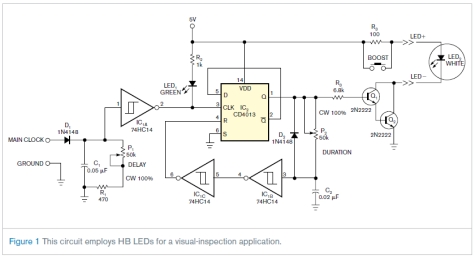
This circuit is not complex, but it was instrumental in an application involving the visual inspection of the spray pattern of fuel injectors for quality and consistency. In this application, xenon strobe lights were unsuitable due to their large...
This article continues the AT90S4433 Microcontroller series. It is recommended to read the previous articles on Atmel Microcontroller programming. This time, a frequency counter is designed to measure frequencies from 1Hz to 100MHz. Alternatively, it can be used to...
In conventional white LED design, the Max1916 low-dropout bias supply for white LEDs serves as a high-performance alternative to simple ballast resistors. The Max1916 is an integrated circuit designed to provide a stable and efficient bias supply for white LEDs....
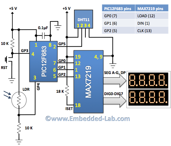
An automatic brightness adjustment is a closed-loop system that has the capability to assess ambient light and adjust the brightness of the display accordingly. The automatic brightness adjustment circuit operates by utilizing a light sensor, typically a photoresistor (LDR) or...
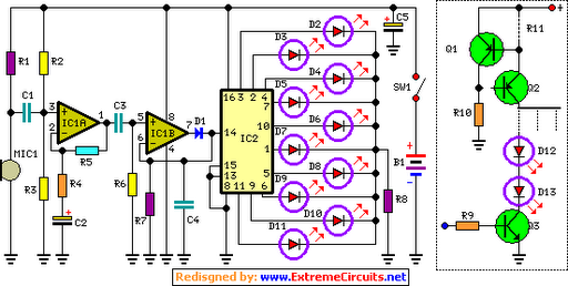
The basic circuit illuminates up to ten LEDs in sequence, following the rhythm of music or speech picked up by a small microphone. The expanded version can drive up to ten strips, each formed by up to five LEDs,...
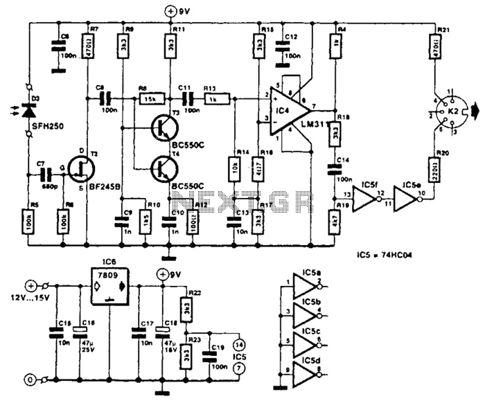
The receiver photodiode SFH250 is utilized to convert optical data pulses at a rate of 32.5 Kbps into electrical signals. The buffer T2 transmits these signals to a cascade amplifier consisting of transistors T3 and T4, followed by an...