
Power operational amplifier integrated circuit

In the context of servo systems, the implementation of a current drive connection serves a critical role in enhancing performance and stability. The relationship between the output current (IOUT) and the input channel number (y) is a fundamental aspect of this configuration, as it establishes a direct proportionality that is essential for accurate control of the servo mechanism.
The current drive mode is particularly advantageous when dealing with motors that exhibit significant inductance. Inductive components can introduce phase shifts that complicate the control dynamics of the servo loop. By employing a current drive approach, these phase shifts can be effectively countered, leading to improved stability and responsiveness of the servo system. This stabilization is vital for applications that demand precise positioning and speed control, such as robotics, CNC machinery, and automated systems.
In a typical schematic for a servo system utilizing current drive, key components include a current sensor, a feedback loop, and control circuitry. The current sensor monitors the output current (IOUT), providing real-time data to the control circuitry. This feedback is crucial for adjusting the input signal based on the current draw of the motor, ensuring that the system operates within desired parameters.
The control circuitry typically employs a PID (Proportional-Integral-Derivative) controller, which processes the input from the current sensor and adjusts the drive signal accordingly. By fine-tuning the PID parameters, the system can achieve optimal performance, minimizing overshoot and settling time while maintaining stability despite the challenges posed by inductive loads.
Overall, the implementation of a current drive connection in servo systems represents a sophisticated approach to managing the complexities of motor control, particularly in high-performance applications where precision and stability are paramount.When used in the servo system, often using the current drive connection. Figure 11-1, the output current IOUT and the input channel number y.. It is proportional. Current drive mode can be reduced because the motor has a large inductance causes a phase shift, help stabilize the servo loop.
Related Circuits
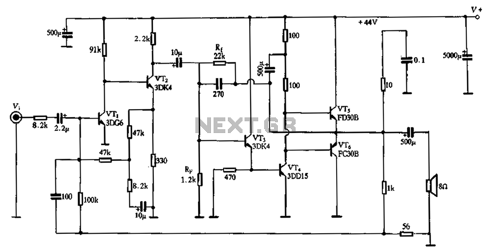
The circuit schematic depicted in Figure 2-3 illustrates a twin direct-coupled input amplifier stage composed of components OV, RLR, and VT2. The emitter of VT2 is connected to the base of VT3, utilizing local feedback to stabilize its DC...

The sound produced imitates the rise and fall of an American police siren. When first switched on, the 10 µF capacitor is discharged, and both transistors are off. When the push button switch is pressed, the 10 µF capacitor...
When this thermometer is utilized in a room environment, it operates intermittently, maintaining this operational state within the temperature measurement circuit due to the stable internal temperature. The astable multiresonance oscillator is composed of transistors VT1 and VT2, forming...
Several RS232 transceiver circuits are used for communication between microcontrollers and other devices, such as PCs or RS232 devices. This document presents a collection of well-known RS232 transceiver circuits. The circuit utilizes the MAX232 from Maxim's devices, which is...
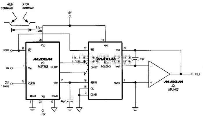
Driving a D/A converter using an A/D converter provides an overall analog-hold function. Although this function has limitations in output resolution, it offers zero voltage droop and infinite hold time. The A/D converter depicted (IC1) features a 12-bit compatible...
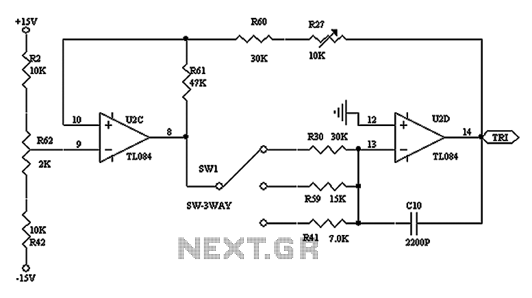
The triangular wave circuit consists of two operational amplifiers (OPs). R62 serves as the offset adjustment, while R27 is utilized for peak adjustment. A switch is included to select different resistances, allowing for the generation of triangular waves at...