
Linear-Circuits in U.H.F. Oscillators

The quarter-wave parallel-wire line serves as an effective tuning unit due to its high quality factor (Q), particularly in the realm of ultra-high frequencies (UHF). This characteristic is crucial for applications where signal purity and stability are paramount. The physical dimensions of the line become manageable when operating at wavelengths around 1 meter, making it suitable for UHF applications. The integration of a quarter-wave line with a vacuum tube oscillator facilitates the generation of high-frequency signals, which can be further optimized by careful circuit design.
In oscillator designs, the choice between parallel and series feeding can influence performance characteristics. The parallel-fed configuration allows for straightforward integration of the quarter-wave line, while series feeding may offer alternative benefits in specific applications. The use of large copper or brass tubes for the quarter-wave line not only aids in minimizing resistive losses but also contributes to the mechanical stability of the assembly.
Adjustability is a key feature of this oscillator configuration. By shifting the shorting bar along the line, the resonant frequency can be fine-tuned to match the desired operating conditions. The placement of the taps for the plate and grid leads is critical; positioning them closer to the shorted end enhances voltage levels at the open end, thereby increasing electrostatic energy and stabilizing oscillations. However, careful consideration must be given to avoid excessive loading, which could lead to circuit instability or oscillation cessation.
The introduction of capacitance at the open end of the quarter-wave line can modify its effective length and tuning characteristics. This adjustment is particularly relevant in high-power applications, such as those involving cyclotrons, where significant radio frequency potentials are generated. The design must account for the impact of parasitic capacitance, which can affect Q and overall circuit performance.
In conclusion, the application of quarter-wave parallel-wire lines in oscillator circuits presents a robust solution for generating ultra-high frequency signals. The design considerations, including component selection, circuit topology, and tuning strategies, are essential for optimizing performance and achieving the desired frequency stability. The integration of symmetrical structures in push-pull configurations further enhances the efficiency and reliability of these circuits in practical applications.The use of a quarter-wave parallel-wire line as a tuning unit has been discussed in the chapter on Short-Lines, where it was pointed out that these " circuits " have comparatively high Q even at the higher frequencies. Their great length ( »/4) prevents their widespread use at lower frequencies. But when the wave-length is only 1 meter or thereabo uts, the line has reasonable physical dimensions. And it is just in these regions that the requirement of high Q becomes difficult to attain with ordinary circuits. Our purpose now is to learn how to connect a quarter-wave line to a vacuum tube to form an efficient oscillator for the production of ultra-high frequencies.
The student should now turn back to Fig. 14 E and study the parallel-fed ultraudion oscillator circuit for a few minutes. Series feed is also possible, as in (a) of Fig. 37 F. The lumped L and C of this circuit is replaced by the quarter-wave line of (b) for u. h. f. Compare (a) and (b) part by part. In general, the LC circuits used in the various types of oscillators of Chapter 14 can be replaced by quarter-wave lines. In the u. h. f. oscillator of Fig. 37 F, large copper or brass tubes may be used for the line. The lead wires to the tube are made as short as possible. The shorting bar can be shifted along the line (within limits) to change the frequency. The plate and grid leads are tapped onto the line as close to the shorted end as possible in order that, for a given voltage from the tube, the open-end voltage may be as high as possible.
The effect is shown in Fig. 37 G. High voltage at the open end means strong electrostatic fields, and this means large electrostatic energy. This is similar to the action of a large flywheel in stabilizing the rotation of a machine. It results in frequency stability in the electrical case. On the other hand, if the tap is too close to the shorted end, the energy from the tube may not be sufficient.
Thus, if a loop of wire is placed near the line to pick up energy for delivery to an antenna, the power output may be so great that the feedback voltages of the tube cannot keep the large storage " tank " filled. Then oscillations cease; the circuit is overloaded. In practice, the taps are shifted toward the shorting bar, with full load on, until oscillations cease.
The tap is moved back a little, or the power supply on the tube is increased until oscillations again take place. It might be added that the impedance of the line is the same when looking in either direction from the taps.
A small capacitance may be connected across the open end of the line in Fig. 37 F. It is then necessary to shorten the physical length of the line in order that its electrical length shall remain one quarter-wave. The losses in the condenser lower the Q of this tuning circuit appreciably. In one application, the capacitance at the open end consists of the " dees " of a cyclotron. R. F. potentials of the order of several hundred thousand volts have been built up between the condenser plates (between the dees) by this method.
It will be noticed in Fig. 37 F, that the filament leads of the u. h. f. circuit contain coils and condensers. The effective or electrical length of this circuit is one-half wave-length. Then the FF terminals will be at the same potential as that at the shorted end of the line. In practice, this condition is found by changing the coils until maximum power output and stability are realized. In general, at the ultra-high frequencies, it is necessary to tune not only the plate and grid circuits but also the filament circuit.
Usually, only two of the three circuits are tuned with high-Q resonant lines. Figure 37 H shows a push-pull circuit in which the grid and plate circuits are tuned with quarter-wave lines, while Fig. 37 I shows a similar circuit with the filament and plate circuits tuned in this manner. These circuits have the advantage of symmetrical structure and increase 🔗 External reference
Related Circuits
A simple network design is a key feature of the Pierce circuit, as illustrated by these 1-MHz oscillators. Operating the crystal slightly above resonance requires only one high-gain transistor stage. Operating it exactly at series resonance requires an additional...
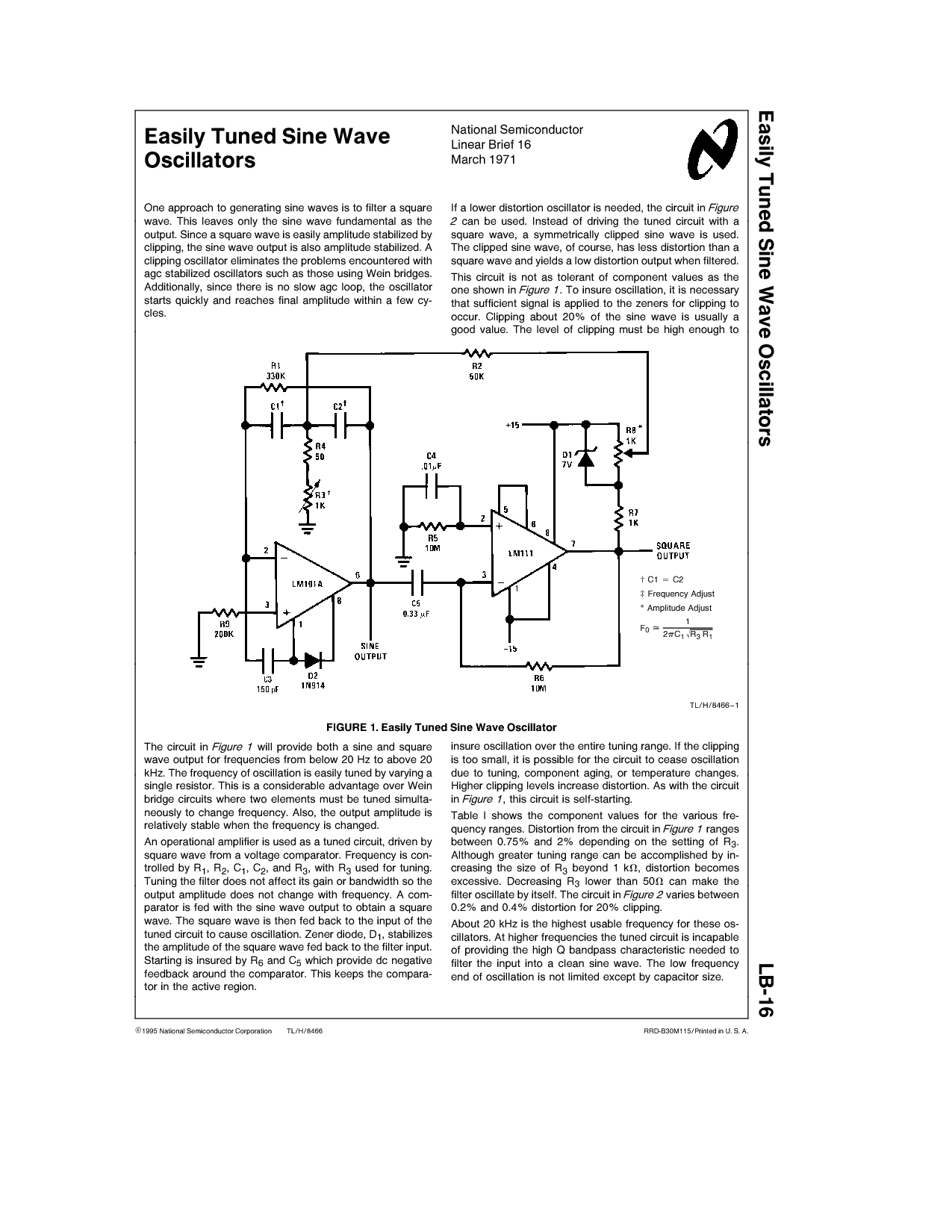
One approach to generating sine waves is to filter a square wave. This leaves only the sine wave fundamental as the output. If a lower distortion oscillator is needed, the circuit in Figure 2 can be used. Instead of...
The RF2516 is a monolithic integrated circuit designed for use as a low-cost AM/ASK transmitter. It is offered in a 16-pin QSOP-16 package and is intended to serve as a phase-locked frequency source for local oscillator or transmitter applications....
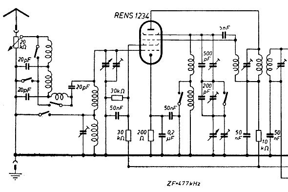
The schematic of the mixer section illustrates an oscillator. The oscillator's LC circuit has only two connections to the valve and does not include a tap or tickler coil. Oscillations will only occur if the tube provides a negative...
This article explains the construction and working of feedback oscillators, with a detailed description of the Wien bridge oscillator and phase shift oscillator, along with their circuit diagrams, basic components, and practical applications. Oscillators are electronic devices that produce...
The emergence of modern radio and radar systems has created a demand for stable harmonic oscillations at specific carrier frequencies to facilitate the necessary modulation and mixing conditions. While early carrier frequencies primarily operated in the low to mid...