
Overspeed indicator
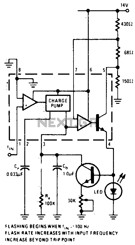
The described circuit employs an operational amplifier configured as a comparator to monitor the output voltage from a converter. The comparator's non-inverting input is connected to a reference DC voltage, while the inverting input receives the output signal from the converter. When the frequency of the input signal exceeds the predetermined threshold of 100 Hz, the comparator output transitions, signaling the LED to illuminate.
In this design, the LM2907 or LM2917 integrated circuits serve as the core components. The LM2907 is a frequency-to-voltage converter that can effectively interpret varying input frequencies, while the LM2917 is a similar device with enhanced features for frequency detection and conversion. The choice of IC depends on the specific requirements of the application, such as response time and output characteristics.
The capacitor C2 plays a crucial role in determining the LED flashing rate. As the frequency of the input signal increases, the average output current from terminal 3 of the comparator rises. This increase leads to a reduction in the time it takes for C2 to charge, thereby increasing the rate at which the LED flashes. This behavior can be observed in applications where visual indicators are needed to represent varying frequencies, such as in audio signal processing or frequency modulation systems.
To ensure reliable operation, proper power supply decoupling and biasing of the op-amp are essential. Additionally, the circuit may include resistors to limit current through the LED and to set the gain of the comparator. Overall, this op-amp comparator circuit provides a straightforward solution for frequency detection and visual indication through LED flashing, making it suitable for various electronic applications.An op-amp comparator is used to compare the converter output with a dc threshold voltage. The circuit flashes the LED when the input frequency exceeds 100 Hz. Increases in frequency raise the average current out of terminal 3 so that frequencies above 100 Hz reduce the charge time of C2, increasing the LED flashing rate IC = LM2907 or LM2917. 🔗 External reference
Related Circuits
This project is a high precision digital thermometer which indicates the temperature on the seven segment display. It has a resolution of 0.06 °C. The 1-wire temperature sensor IC from Maxim semiconductors is used as the sensor. The DS18S20...
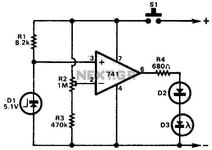
A 741 operational amplifier is utilized as a voltage comparator. The non-inverting input is connected to a zener reference source, providing a reference voltage of 5V. Resistor R2 is calibrated so that the voltage at the inverting input is...
The entire project was developed at the request of a friend. Its purpose is to remotely monitor the water level in a metal tank located in the attic using a simple control unit placed in the kitchen, several floors...
The image depicts an ultrasonic liquid level indicator circuit. This circuit consists of an ultrasonic transmitter circuit and a receiver circuit. The ultrasonic transmitter circuit includes a 555 timer, resistor R1, variable resistor W1, capacitor C1, and the ultrasonic...
The circuit activates a light corresponding to the first button pressed in a "Who's First" game. While three stages are illustrated, the circuit can be expanded to accommodate any number of buttons and lights. The circuit design employs a series...

This simple circuit indicates the status of a phone, including Line OK, Dialing, and Call Attended. It also features a locking mechanism to block outgoing calls while allowing incoming calls, preventing misuse of the telephone. The circuit requires only...