
Battery condition indicator

The circuit employs a 741 operational amplifier configured as a voltage comparator. The primary function of this configuration is to compare the voltage at its non-inverting input (V+) with the voltage at its inverting input (V-). The non-inverting input is connected to a zener diode, which stabilizes the reference voltage at 5V. The inverting input is set to receive half of the supply voltage through a voltage divider network formed by the resistor R2.
In operation, when the supply voltage is above 10V, the voltage at the inverting input will be 5V (half of the supply voltage), which is equal to the reference voltage at the non-inverting input. In this condition, the output of the op-amp remains low, and the LED remains off. When the supply voltage decreases below 10V, the voltage at the inverting input drops below 5V, making the non-inverting input higher than the inverting input. This condition results in the op-amp output transitioning to a high state, which activates the LED.
The design allows for flexibility in setting the threshold voltage by adjusting the value of R2. By changing R2, the voltage at the inverting input can be manipulated to create different activation points for the LED, allowing the circuit to signal different voltage levels based on the application requirements. The LED serves as a visual indicator of the supply voltage status, providing immediate feedback on the circuit's operational state. This simple yet effective design is useful in various applications where monitoring supply voltage is critical.A 741 op amp is employed as a voltage comparator. The noninverting input is connected to zener reference source. Reference voltage is 5V. R2 is adjusted so that the voltage at the inverting input is half the supply voltage. When supply is higher than 10V, the LED will not light. When the supply falls just fractionally below the 10V level, the IC inverting input will be slightly negative of the noninverting input, and the output will swing fully positive The LED will light, indicating that the supply voltage has fallen to the preset threshold level. The LED can be made to light at other voltages by adjusting R2.
Related Circuits
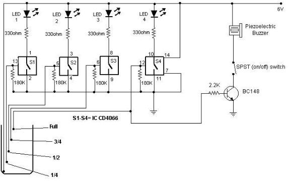
A simple and cost-effective water level indicator circuit can be designed using this schematic. This water level indicator utilizes a CMOS IC CD4066 to indicate the amount of water present in an overhead tank and to provide an alarm...
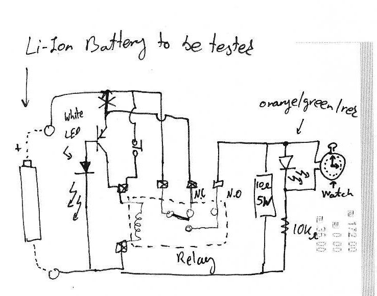
It is assumed that individuals interested in constructing this circuit can interpret the schematics provided below. Basic principles: Note that lithium-ion batteries should not be discharged below 3V. The circuit design focuses on the safe operation of lithium-ion batteries, particularly...

There are many applications where the accuracy of a digital or analog (bar graph) output is not necessary, but a solution that offers more than a simple low/high indicator is desirable. In various electronic applications, there exists a need for...
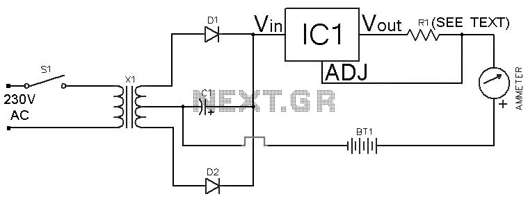
This Ni-Cd battery charger is a circuit utilizing the LM317 regulator IC. The design is straightforward and requires minimal components. By adjusting the value of resistor R1 between 1 ohm and 120 ohms, the charging current can be modified...
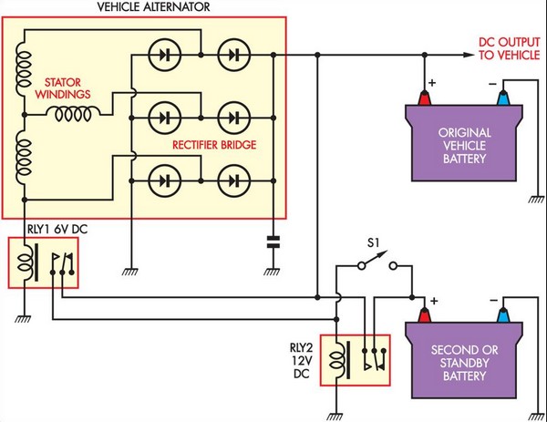
This circuit is straightforward and utilizes a 6V supply from one of the stator connections of the vehicle's alternator. This supply is connected to a 6V automotive relay (RLY1), which controls a Continuous Duty Solenoid (RLY2). The solenoid serves...
LVDT (linear voltage differential transformer) is widely used as a linear position sensor. The AD589 integrated circuit provides a complete solution for LVDT. The Linear Voltage Differential Transformer (LVDT) is a highly precise sensor commonly employed for measuring linear displacement....