
Ultrasonic Liquid Level Indicator Circuit Composed Of NE555

The ultrasonic liquid level indicator operates by emitting high-frequency sound waves from the ultrasonic transmitter head (UCM40T). The 555 timer functions as an oscillator, generating a pulse signal that drives the transmitter. Resistor R1 and variable resistor W1 are used to adjust the frequency and duty cycle of the output signal, while capacitor C1 helps to stabilize the oscillation.
When the sound waves emitted by the transmitter encounter the liquid surface, they are reflected back towards the receiver head (UCM40R). The receiver detects these reflected sound waves and converts them into an electrical signal. The cascade amplifier (BG1) amplifies this signal for further processing. The time taken for the sound waves to return is proportional to the distance between the transmitter and the liquid surface, allowing for accurate measurement of the liquid level.
This circuit can be utilized in various applications, including water tanks, industrial processes, and other areas where liquid level monitoring is essential. The design allows for non-contact measurement, minimizing maintenance and ensuring reliability in diverse environments. Proper calibration of the components is critical to achieve optimal performance and accuracy in liquid level detection.The picture shows the ultrasonic liquid level indicator circuit. This circuit is made up of ultrasonic transmitter circuit and receiver circuit.The ultrasonic transmitter circuit is made up of 555, R1, W1, C1 and ultrasonic transmitter head UCM40T. The ultrasonic receiver circuit is made up of the corresponding receiving head UCM40R, cascade amplifier BG1..
🔗 External reference
Related Circuits
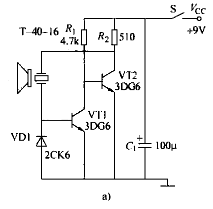
The ultrasonic transmitter circuit T-40-16, along with various discrete components, functions as a feedback sensor. The transistors VT1 and VT2 create a robust positive feedback oscillator that converts an electric signal into an ultrasonic oscillation signal, with the oscillation...

The circuit serves as a signal source for calibration level meters or sensor-driven differential transformers. The oscillation frequency is determined by the 74HC04, producing a frequency of 1 kHz through resistor R. The supply voltage of the circuit changes...
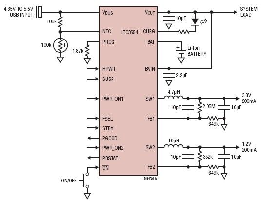
This micropower multifunction power management integrated circuit (PMIC) is designed using the LTC3554, manufactured by Linear Technology Corporation. It serves as a solution for portable Li-Ion Polymer battery-based applications. The LTC3554 integrates a USB-compatible linear PowerPath manager, a standalone...
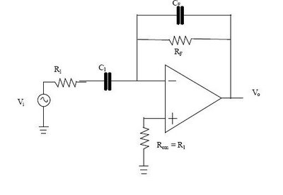
The differentiator circuit is an application circuit derived from mathematical principles influenced by capacitor behavior. The circuit, as illustrated in the accompanying image, is a simple differentiator configuration. To derive the differentiator formula, the following sequence is used: Ic...
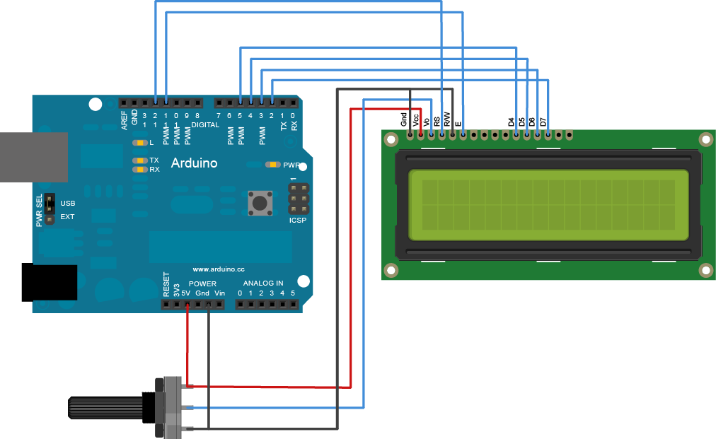
The Liquid Crystal Library enables control of LCD displays compatible with the Hitachi HD44780 driver. Many such displays are available, typically identifiable by their 16-pin interface. It is advisable to solder a pin header strip to the 14 (or...
Trimming is straightforward when matched NPN transistors are utilized for Q1 and Q2, along with 1% tolerance resistors for R6 to R11. A dual trace oscilloscope, digital voltmeter (DVM), and sine wave generator are required for this process. Although...