
autonomous car

The autonomous vehicle design described involves a systematic approach to navigating a predefined path using optical sensors and microcontroller technology. The reflective phototransistors serve as the primary sensing mechanism, providing feedback on the vehicle's position relative to the line on the ground. The Atmel 8515 microcontroller processes this feedback and executes control commands to steer the vehicle accordingly. The use of a solenoid for steering introduces a binary control mechanism, which simplifies the steering process but may limit precise maneuverability.
The H-bridge configuration allows for efficient control of the drive motor and steering solenoid, providing the necessary current to enable effective operation. The choice of BJTs for the H-bridge design is appropriate given their ability to handle high current loads while maintaining reliability. The implementation of wire-wrapping for the circuitry ensures a robust construction suitable for the mobile application, minimizing the risk of disconnections that could occur with breadboard setups.
The power supply design, with separate voltages for logic and motor operations, is critical in preventing interference from motor noise that could disrupt the logic operations. The use of an open-loop-gain amplifier to convert the phototransistor output to a logic level is a suitable solution for achieving the necessary signal processing. Calibration through the use of trim-pots and LEDs enhances the system's adaptability to varying environmental conditions.
Overall, this project exemplifies a practical application of electronics and control systems in the development of autonomous vehicles, highlighting the integration of sensors, microcontrollers, and power management in achieving functional and efficient designs.Autonomous vehicles are already in use in many manufacturing facilities, and they are also sold as toys. Perhaps one day, the world`s highways will be filled with cars requiring no user intervention. While we are not there yet, and may never get there, an autonomous vehicle can serve as a very interesting and practical design exercise.
Our vehicle uses optical sensors to follow a line on the floor. Some autonomous vehicles used in manufacturing use a similar concept, following magnetic strips embedded in the factory floor. The versatility of an optical design should be readily apparent, since re-routing the vehicle requires no more than re-painting a line.
Our vehicle uses reflective phototransistors to follow a line on the ground beneath it. The state of the phototransistors is captured, and the car is controlled accordingly by an Atmel 8515 microcontroller. If the car detects a small deviation from the line, it will correct its path by steering in the appropriate direction.
If it detects a large deviation, it will take more "drastic" measures to correct its path: it will back up while steering itself back towards the line until it re-centers itself. It then continues on its path. The original objective for this project was to optimize the car for the speed with which it navigated the line.
To do this, we would have increased the speed when little compensation was needed, and decreased the speed as more was needed. This optimization, however, did not require much more effort on our part than the heuristic outlined above.
This is because the speed is mechanically regulated by the gradual acceleration of the car in balance with the direction reversal for large corrections. The hardware for this project was the bulk of the work. Because we were making a moving vehicle, we decided that it would be best not to have any of the circuitry on breadboards.
Breadboards are also expensive, so we probably would have had to disassemble the car after its demonstration. We therefore chose to wire-wrap all of the circuitry. This required a fair amount of labor, but it was well worth it in the end. The car we selected is fairly simple to operate. It has a rear wheel drive, complete with a differential, which is powered by a DC motor. The steering is not controlled by a servo, but rather by a solenoid. This results in an "all or nothing" control over the steering, but we did not find this to be overly constraining.
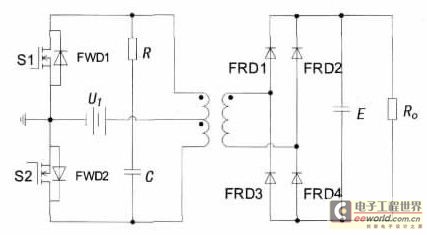
We built two H-bridges using TIP-31, TIP3055, and TIP-42 BJTs to deliver power to the steering and the drive motor. Because of the current requirements (the drive motor and steering solenoid could draw several amps), we used 20-gauge wire for the high-current areas of the H-bridges rather than the 30-gauge wire used for the rest of the circuit.
Schematicsof the H-bridges and supporting CMOS logic appear below. To detect the line, we use an array of five reflective photo-sensor pairs manufactured by Fairchild Semiconductor. We mounted them just ahead of the front wheels on a threaded rod to allow us to reposition them as necessary.
The current through the photo-transistor depends on the intensity it detects, but what we really need is a logic level output. We therefore used an open-loop-gain amplifier made from an LMC7111 op-amp. A trim-pot allowed us to set a threshold level, and LEDs were used to aid in calibration. Aschematicof the circuit used for the photo-sensors appears below. Because of the high current draw from the motor and steering, we decided to use a separate power supply for the logic.
The logic runs on 6V while the car`s motors run on 12V. This initially resulted in some careless bugs, but we seem to have avoided problems with any inductive "kick" from the motor a 🔗 External reference
Related Circuits
With the increase in the variety of modern electrical equipment for vehicles and the rise in power levels, there is a growing demand for different types of power supplies, including AC and DC sources. The power system needs to...
All car batteries require a 12V battery charger, which also applies to marine, RV, and power sports batteries. The high-efficiency lead-acid batteries available today necessitate more effective charging techniques. The battery charger is a crucial tool for prolonging battery...
The Car LED Light Sequencer utilizes a standard 74C164 8-bit shift register as its main component. The 74C164, also referred to as an 8-Bit Parallel-Out Serial Shift Register, is a monolithic complementary MOS (CMOS) integrated circuit. This 8-bit shift...
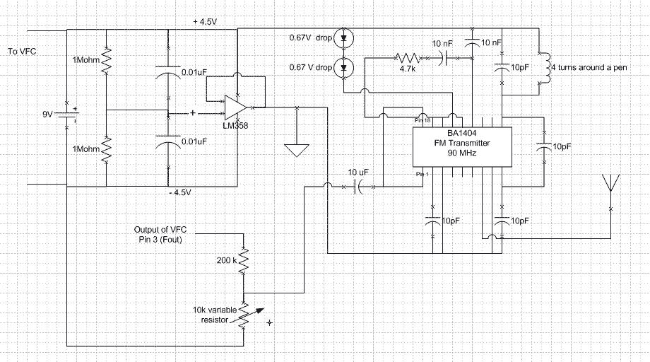
V_logic is connected to the power supply Vs and all ground are connected to the negative terminal of the battery. Fout is a square wave of varying frequency with a maximum amplitude of Vs. A voltage divider is needed...
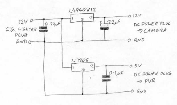
There is now no need for a separate camera and recorder; for a lower cost, an integrated dash camera that records in HD can be obtained. The Techmoan blog offers reviews on these devices. This text describes the installation...

This design uses a smart card to enable a relay. A Nutchip recognizes its mating smart card among thousand similar ones, because you choose the code to be programmed in the card's memory. No specialized knowledge is necessary, as...