
Auxiliary Negative Dc Supply

The circuit employs the CD4009 integrated circuit, which is a hex inverter capable of generating square-wave signals. The frequency of oscillation is dictated by the values of C1 and R1, which create an RC timing network. The oscillation frequency can be adjusted by changing the capacitance of C1 or the resistance of R1, allowing for flexibility in applications requiring different frequencies.
The output from the oscillator is then processed by a rectifying stage formed by C2, D1, D2, and C3. The diodes D1 and D2 are configured to rectify the AC signal generated by the oscillator into a pulsating DC signal. Capacitor C2 acts as a filter capacitor, smoothing the output to reduce ripple voltage, while capacitor C3 may serve as an additional filtering stage to stabilize the output voltage.
The resulting output voltage from this circuit is approximately -3.5 Vdc, which can be utilized in various electronic applications that necessitate a negative voltage supply, such as biasing for certain types of transistors or operational amplifiers. This circuit is particularly useful in scenarios where only positive DC voltages are available, providing a simple and efficient solution for generating a negative voltage supply. In this circuit, IC1 (CD4009) is used as a square-wave oscillator at approx imately 25 kHz. CI and Rl set this frequency. C2, Dl, D2, and C3 form a p-p rectifier, which outputs about -3.5 Vdc. This circuit should be useful where a small negative dc supply is required, but only positive dc voltages are available.
Related Circuits
Using the versatile L200 voltage regulator, this power supply has independent voltage and current limits. The mains transformer has a 12volt, 2 amp rated secondary, the primary winding should equal the electricity supply in your country, which is 240V...

This 15V variable power supply electronic project is designed using 2N3055 transistors. The output voltage of this variable power supply can be adjusted in the range between 1.5 and 15 volts. This 2N3055 15V variable power supply can provide...
It's a variable power supply based on an LM317 voltage regulator. The range of power is between 1.6 and 13.5 volts, and it can provide up to 1.5 Amps if supplied with an adequate cooler, such as an aluminum...
This constant current constant voltage switched-mode power supply (SMPS) is designed for efficient battery charging. The circuit outputs a constant voltage of 7.2V and a constant current of 600mA. The operation mechanism is straightforward: when the load impedance is...
Rsense will cause Q2 to conduct when a threshold of approximately 0.65V is reached. Rbias will determine the extent of this limitation, although this aspect remains unclear. Particularly, if Rsense is positioned on the high side, simply activating Q2...
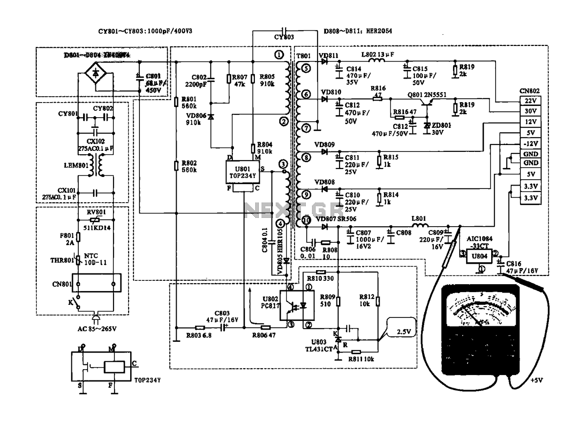
The Coship CDVB3188V receiver features a switching power supply circuit similar to the CDVB3188C model. The circuit includes several key components: an AC input circuit, an anti-jamming filter circuit, a complete flow filter circuit, and a switching oscillation circuit....