
Avenger Sebring Coupe Stratus Coupe 1999 2006

The power top system utilizes a combination of electronic and hydraulic components to facilitate the operation of the convertible top. The initial step in diagnosing issues within this system is to utilize a scan tool, which interfaces with the vehicle's onboard diagnostics. This tool assesses the integrity of the PCI data bus, ensuring that communication between the BCM and other electronic modules is intact. If the scan tool indicates that the PCI bus is functioning correctly, further investigation into the power top motor and its associated wiring should be conducted.
The use of a 12-volt test light is critical for verifying the operation of the UP and DOWN relay control circuits. This testing method confirms that the BCM is sending the appropriate signals to the relays, which in turn energize the power top motor. If the test light does not illuminate in either the UP or DOWN positions, it indicates a potential fault in the wiring or the BCM itself.
The power top switch plays a pivotal role in the operation of the convertible top. It is directly connected to the BCM, which interprets the input from the switch and controls the operation of the power top motor through a relay system. The multiplexed signal sent to the switch allows for variable resistance based on the switch position, enabling the BCM to determine the desired action, whether raising or lowering the top.
In the second detent position, the system's design allows for simultaneous operation of the convertible top and all four windows. This feature enhances user convenience and ensures that the windows are lowered sufficiently to avoid damage during the top's operation. The requirement for the operator to raise the windows back to the fully closed position after the top is up is a necessary safety feature to maintain the vehicle's integrity.
Overall, thorough diagnostics of the power top system should include checks for hydraulic fluid levels, electrical continuity, and the operational integrity of all components involved, ensuring a reliable and efficient convertible top operation.Any diagnosis of the power top system should begin with the use of a scan tool and the proper Diagnostic Procedures Information. The scan tool can provide confirmation that the Programmable Communications Interface (PCI) data bus is functional, that all of the electronic modules are sending and receiving the proper messages on the PCI data bus, an
d that the power top motor is being sent the proper hard wired output by the Body Control Module (BCM). Place a 12-volt test light between the fused B+ and power top UP relay control terminals in the harness side of the connector.
With the ignition switch in the RUN position, operate the power top switch in the UP direction. The test light should light. Place a 12-volt test light between the fused B+ and power top DOWN relay control terminals in the harness side of the connector. With the ignition switch in the RUN position operate the power top switch in the DOWN direction. The test light should light. Turn the ignition switch to the OFF position. Disconnect the BCM. Using an ohmmeter, check for continuity on the power top UP and DOWN circuits between the BCM and the power top relay assembly.
Continuity should be present. The power top system allows the convertible top to be raised and lowered electrically by actuating a switch in the center floor console. The power top system receives battery feed through a fuse in the Power Distribution Center (PDC) when the ignition switch is in the ON position.
The power top motor is part of the motor/hydraulic pump assembly and cannot be serviced separately. If the motor is inoperative, the complete assembly must be replaced. The power top switch is hard wired to the Body Control Module (BCM) through the Power Top Switch Mux circuit. The BCM supplies a multiplexed voltage of approximately 90 percent of the ignition voltage to the power top switch.
Through a series of resistors, the power top switch switches the circuit to ground. The circuit resistance is varied depending on the switch position. When a top operation input is received by the BCM, it will ground the respective power top relay control circuit which in turn will operate the power top motor. If the power top switch is pressed and held to the down position second detent, the BCM will command the window drop relay assembly to drop all the windows to the fully down position.
Top Down/4 Window Down -This is the second detent on the switch. Holding the switch in this position lowers the convertible top and commands all 4 windows down simultaneously. The switch must be held in this position. Top Up -Holding the switch in this position raises the convertible top to the closed position. It will also lower all 4 windows approximately 3 inches to prevent seal damage. The windows must be raised to the full-up position by the vehicle operator. The convertible top will raise slowly or make abnormal noise if the hydraulic fluid level is low. Always ensure the hydraulic fluid level is within specifications prior to component replacement. Any diagnosis of the power top system should begin with the use of a scan tool and the proper Diagnostic Procedures Information.
The scan tool can provide confirmation that the Programmable Communications Interface (PCI) data bus is functional, that all of the electronic modules are sending and receiving the proper messages on the PCI data bus, and that the power top motor is being sent the proper hard wired output by the Body Control Module (BCM). If the problem being diagnosed is an inoperative power top switch illumination lamp, but the power top switch operates as designed, replace the power top switch.
Using an ohmmeter, test the resistance measured between pins 2 & 3 of the power top switch. Check the resistance in each switch position and compare these readings to the following chart. If the resistance is according to specification, use a scan tool and the proper Diagnostic Procedures Informatio 🔗 External reference
Related Circuits
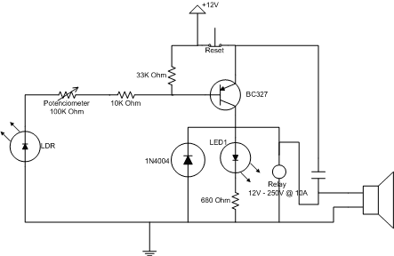
The purpose of this project is to study the environmental response to human actions. An environment was created with several visible laser beams. If one of these beams is interrupted (for example, if someone crosses it), an alarm will...
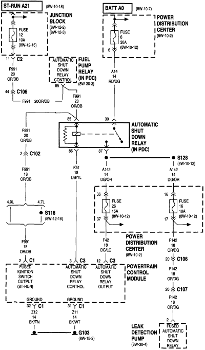
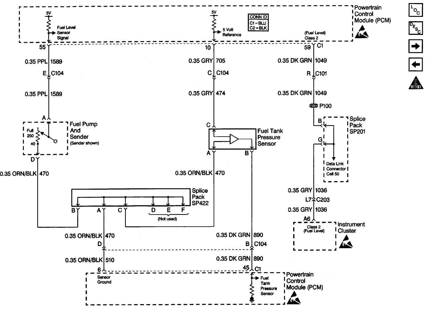
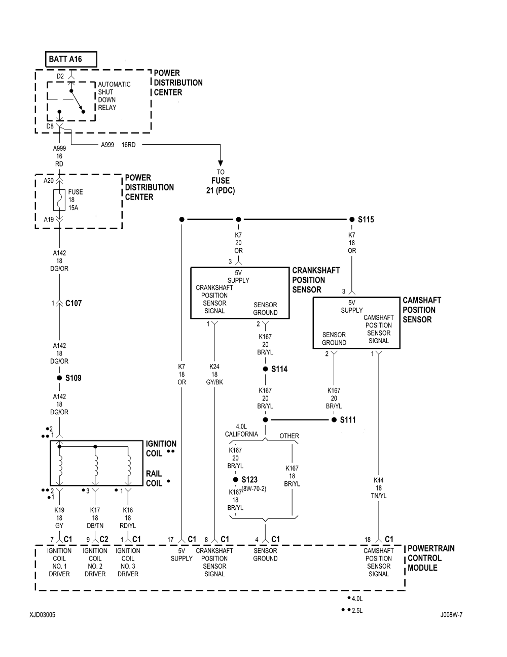
1999 Jeep Cherokee Fuel Pump Wiring Diagram. The wiring diagram for the fuel pump in a 1999 Jeep Cherokee provides a visual representation of the electrical connections and components involved in the fuel delivery system. This diagram is essential for...
A 1999 S10 2.2L Fuse Box inquiry involves identifying the main power terminals located at the top left and right of the Fuse Box. The question pertains to which terminal serves as the full-time power terminal and which one...
While driving the car, the gauges turn off and the car stalls immediately. The car will not start until the gauges come back on. When the gauges are off, the car starter will turn over the engine, but it...

The power amplifier IC TDA2006 provides high output current and has very low harmonic and cross-over distortion. Furthermore, the device incorporates an original (and patented) short circuit protection system that automatically limits the dissipated power to keep the working...
The wiring diagram for the clock and radio screen illumination for a 1999 Mercury Sable with a 3.0L VIN U. The vehicle is a Mercury Sable GS, not LS. Assistance is required to identify which circuit in the diagrams...