
AVR 1.1V Internal ADC Reference Over-Voltage

The analog-to-digital converter (ADC) in microcontrollers plays a vital role in interfacing with the analog world. The reference voltage (VREF) is fundamental in determining the range of analog inputs that can be accurately converted to digital values. When the internal 1.1V reference is selected, any analog signal exceeding this voltage will result in a maximum digital output, typically represented by the binary value 0x3FF (or 1023 in decimal for a 10-bit ADC). This behavior is known as clipping, where the ADC cannot represent input values beyond its reference range.
It is critical to differentiate between the voltage reference and the absolute voltage limits of the microcontroller. The VREF serves as a benchmark for the ADC's conversion process, while the voltage limit, typically defined by the supply voltage (AVcc), indicates the maximum voltage that can be safely applied to the ADC input pins. Exceeding AVcc can potentially damage the microcontroller, although many designs incorporate protective measures, such as clamping diodes, which can help mitigate the risk of damage from overvoltage conditions.
In practical applications, it is advisable to design the external circuitry to ensure that the input voltages remain within safe limits, ideally below AVcc. This approach not only protects the microcontroller but also ensures reliable operation of the ADC. In scenarios where it may be necessary to exceed the VREF, careful consideration should be given to the implications on accuracy and potential risks. Overall, understanding the relationship between the reference voltage, voltage limits, and the ADC's behavior is essential for effective microcontroller design and implementation.If I use the internal 1. 1V reference for the ADC, and my Analog input exceeds 1. 1V, lets say 2. 5V, is that harmful to my microcontroller Or will ADC value simply clip (to 0x3FF) at 1. 1V Speaking from experience alone, not from datasheet references, so be careful: I`ve used internal ref and accidentally connected ADC pin to 4 Volts+ for hours. It`ll clip, but won`t kill the MCU. Anindo Ghosh Dec 11 `12 at 19:42 The reference voltage for the ADC (VREF) indicates the conversion range for the ADC. Single ended channels that exceed VREF will result in codes close to 0x3FF. VREF can be selected as either AVCC, internal 1. 1V reference, or external AREF pin. A voltage reference in a microcontroller is not the same as a voltage limit. The voltage reference (in this case) is used by the ADC to perform a comparison, and the microcontroller appears to be designed to allow you to exceed this amount.
You never want to exceed the voltage limit (in this case, that would be AVcc, the ADC`s analog power supply). Microcontrollers have built-in protection diodes to save your bacon if that happens, but generally speaking, one should design the external circuit so that it does not exceed the voltage limit.
(This is a best practice; in some cases, one may have reasons to ignore it. ) 🔗 External reference
Related Circuits
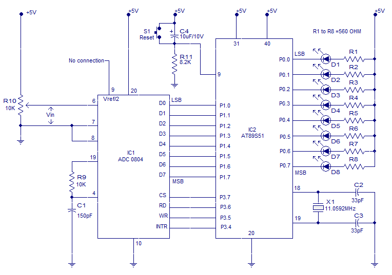
The ADC (Analog to Digital Converter) is a crucial component in numerous embedded projects. This article focuses on interfacing an ADC with the 8051 embedded controller. The ADC0804 model is utilized, and before detailing the interfacing procedure, it is...
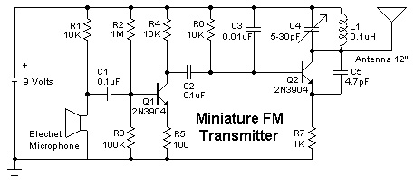
Construct a simple mini FM transmitter. This engaging project demonstrates how to create a mini broadcasting transmitter capable of transmitting an audio signal up to a quarter mile to any FM receiver. It is straightforward to assemble and offers...
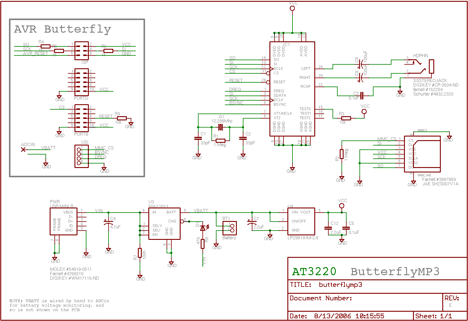
AVR ISP interface (optional but useful if the bootloader is not preferred, if budget constraints prevent the use of JTAG, or if AVR Studio has crashed and disabled on-chip debugging). The following is the updated bill of materials for...
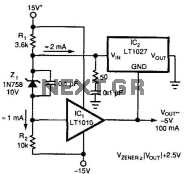
A method for enhancing the output current of a reference while also providing overload protection is illustrated. In this configuration, IC1 functions as a power buffer. The LT1027 regulates the output voltage (Vout) and ground to maintain a stable...
The primary target audience of the USB08 Reference Design consists of developers focused on microcontroller firmware and hardware, as well as those dealing with Windows driver and application software issues. USB (Universal Serial Bus) serves as a standardized bus...
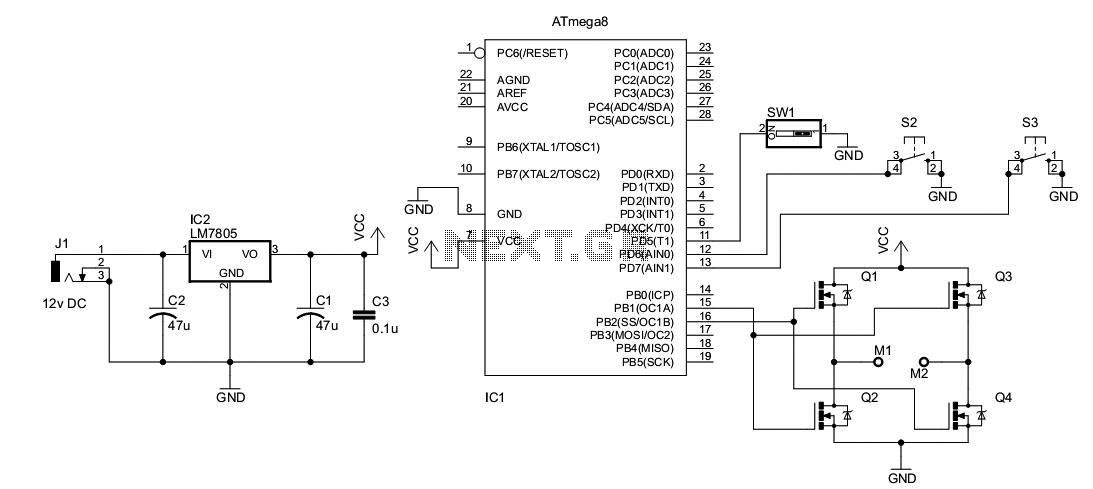
A DC motor from an old personal stereo cassette player has been utilized in this circuit, which provides control over both the speed and direction of the motor. The circuit employs PWM waveforms to drive a MOSFET H-bridge, as...