
Power Buffer Boosts Reference Current

The described circuit employs an LT1027 integrated circuit (IC) to serve as a power buffer, which is essential for increasing the output current capability of a voltage reference. The role of the LT1027 is to maintain a stable 5 V output while isolating the load from the voltage reference source. This configuration is particularly beneficial in applications where the load may vary significantly, as it allows the reference voltage to remain unaffected by changes in the load current.
The RC damper, composed of a 50-ohm resistor and a 0.1 µF capacitor, is critical for ensuring the stability of the feedback loop. This damper mitigates potential oscillations that could arise due to feedback instabilities, particularly when driving capacitive loads. Oscillation can occur when using low equivalent series resistance (ESR) capacitors, which are common in ceramic and mylar types. To prevent such issues, the circuit design recommends the use of aluminum electrolytic or tantalum capacitors, which typically exhibit higher ESR values and thus contribute to improved stability in this application.
In summary, the circuit effectively enhances the output current capability of a reference voltage while ensuring reliability through overload protection and stability measures. Proper component selection, particularly regarding capacitors, is crucial for maintaining the desired performance and preventing oscillation. A method of boosting the output current of a reference and also protecting against overloads is shown in Fig. 66-5. IC1 acts as a power buffer. The LT1027 forces the output of V0ut and ground to be 5 V. The RC damper (50 and 0.1 ¥) provides loop stability. The output might oscillate if low ESR capacitors are connected to it, so use aluminum electrolytic or tantalum capacitors instead of ceramic or mylar.
Related Circuits

It may be easy to find a precision voltage reference for your application; however, a programmable precision reference is another matter. The circuit in Figure 1 yields a precision reference with an LSB of 62.5 µV. The circuit is...
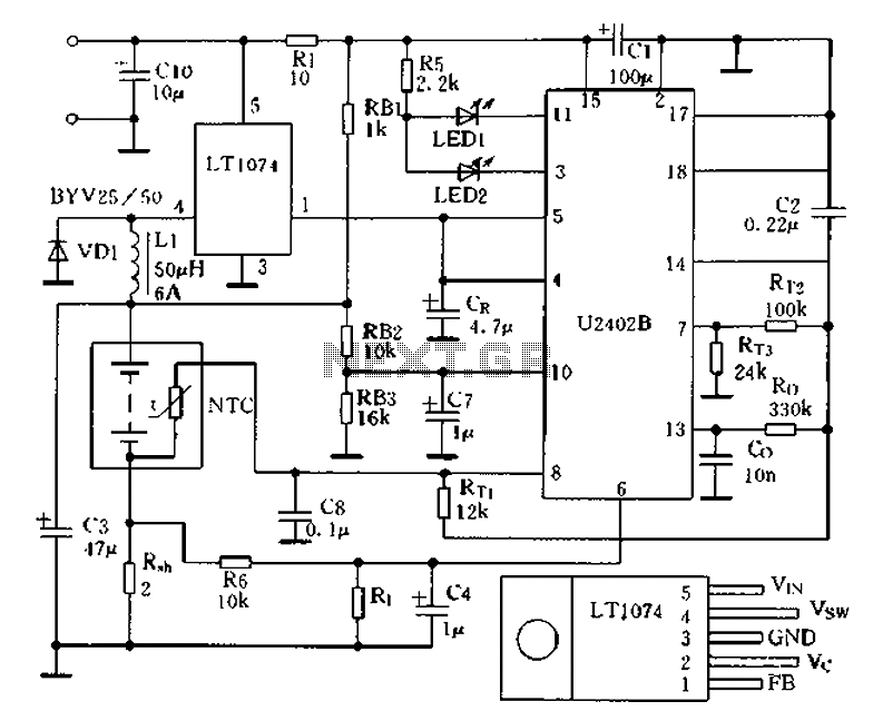
Charging circuit from the DC power supply switching power supply control The charging circuit described is designed to operate with a DC power supply, utilizing a switching power supply control mechanism. This type of circuit is commonly employed in applications...
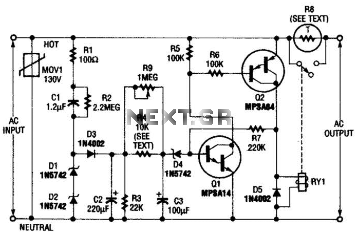
Q1 is an NPN Darlington transistor, and Q2 is a PNP Darlington transistor. MOV1 is a metal-oxide varistor, while R8 is a thermistor used for limiting inrush current. This circuit is designed to limit AC line current to a...

The adjustable power supply can be reconfigured by changing the value of V2 and enhancing other components as needed. The output voltage is calculated using the formula Vnm = 1.25 (1 + R2/R^). Additionally, R2 can be modified as...
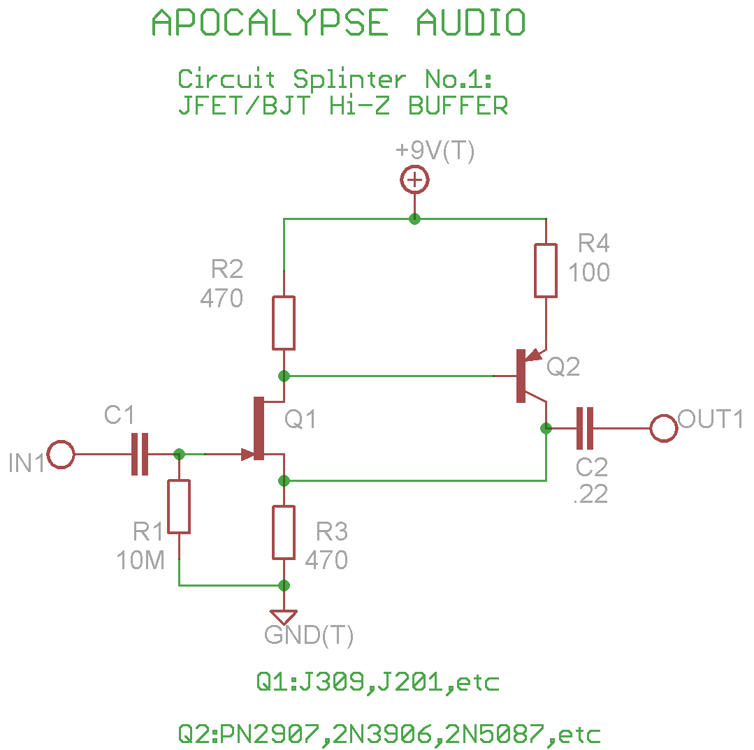
This is a common circuit often found in various resources, yet it appears to be less prevalent in stompbox applications. The circuit utilizes an NPN JFET DC coupled with a PNP BJT. The FET provides a significantly higher input...
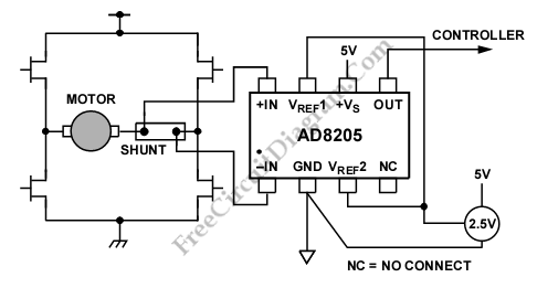
A differential current sensing circuit is integrated within an H-bridge configuration, as illustrated in the schematic diagram below. This circuit exemplifies the application of the AD8205, which is capable of measuring current in both directions as the motor changes...